Download
1 / 20
770 likes | 5.81k Views
Chapter 6. Dielectrics and Capacitance. Boundary Conditions for Perfect Dielectric Materials. Consider the interface between two dielectrics having permittivities ε 1 and ε 2 , as shown below.

E N D
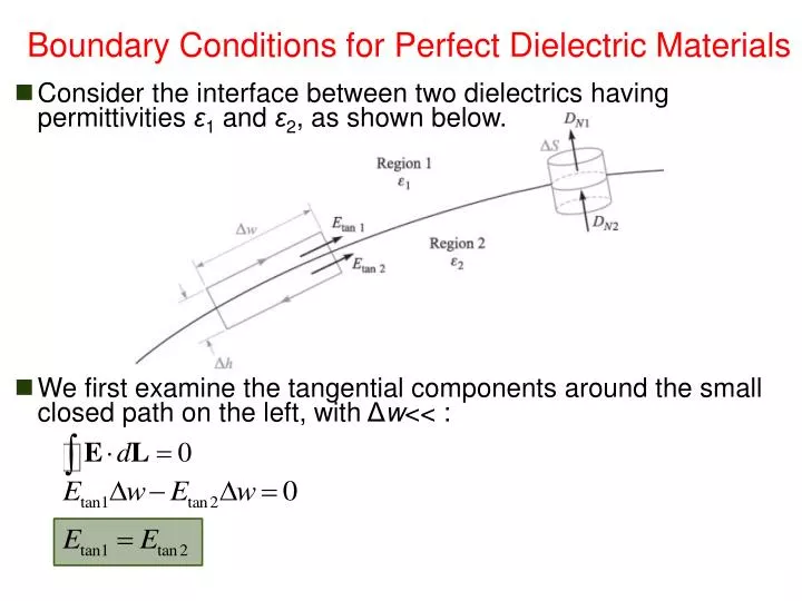
Chapter 6 Dielectrics and Capacitance Boundary Conditions for Perfect Dielectric Materials • Consider the interface between two dielectrics having permittivities ε1 and ε2, as shown below. • We first examine the tangential components around the small closed path on the left, with Δw<< :
Chapter 6 Dielectrics and Capacitance Boundary Conditions for Perfect Dielectric Materials • The tangential electric flux density is discontinuous, • The boundary conditions on the normal components are found by applying Gauss’s law to the small cylinder shown at the right of the previous figure (net tangential flux is zero). • ρS cannot be a bound surface charge density because the polarization already counted in by using dielectric constant different from unity • ρS cannot be a free surface charge density, for no free charge available in the perfect dielectrics we are considering • ρS exists only in special cases where it is deliberately placed there
Chapter 6 Dielectrics and Capacitance Boundary Conditions for Perfect Dielectric Materials • Except for this special case, we may assume ρS is zero on the interface: • The normal component of electric flux density is continuous. • It follows that:
Chapter 6 Dielectrics and Capacitance Boundary Conditions for Perfect Dielectric Materials • Combining the normal and the tangential components of D, • After one division,
Chapter 6 Dielectrics and Capacitance Boundary Conditions for Perfect Dielectric Materials • The direction of E on each side of the boundary is identical with the direction of D, because D = εE.
Chapter 6 Dielectrics and Capacitance Boundary Conditions for Perfect Dielectric Materials • The relationship between D1 and D2 may be found from: • The relationship between E1 and E2 may be found from:
Chapter 6 Dielectrics and Capacitance Boundary Conditions for Perfect Dielectric Materials • Example • Complete the previous example by finding the fields within the Teflon. • E only has normal component
Chapter 6 Dielectrics and Capacitance Boundary Conditions Between a Conductor and a Dielectric • The boundary conditions existing at the interface between a conductor and a dielectric are much simpler than those previously discussed. • First, we know that D and E are both zero inside the conductor. • Second, the tangential E and D components must both be zero to satisfy: • Finally, the application of Gauss’s law shows once more that both D and E are normal to the conductor surface and that DN = ρS and EN = ρS/ε. • The boundary conditions for conductor–free space are valid also for conductor–dielectric boundary, with ε0 replaced by ε.
Chapter 6 Dielectrics and Capacitance Boundary Conditions Between a Conductor and a Dielectric • We will now spend a moment to examine one phenomena: “Any charge that is introduced internally within a conducting material will arrive at the surface as a surface charge.” • Given Ohm’s law and the continuity equation (free charges only): • We have:
Chapter 6 Dielectrics and Capacitance Boundary Conditions Between a Conductor and a Dielectric • If we assume that the medium is homogenous, so that σ and ε are not functions of position, we will have: • Using Maxwell’s first equation, we obtain; • Making the rough assumption that σ is not a function of ρv, it leads to an easy solution that at least permits us to compare different conductors. • The solution of the above equation is: • ρ0 is the charge density at t = 0 • Exponential decay with time constant of ε/σ
Chapter 6 Dielectrics and Capacitance Boundary Conditions Between a Conductor and a Dielectric • Good conductors have low time constant. This means that the charge density within a good conductors will decay rapidly. • We may then safely consider the charge density to be zero within a good conductor. • In reality, no dielectric material is without some few free electrons (the charge density is thus not completely zero), but the charge introduced internally in any of them will eventually reach the surface. ρv ρ0 ρ0/e ε/σ t
Chapter 6 Dielectrics and Capacitance Homework • No homework this week.
Chapter 6 Dielectrics and Capacitance Capacitance • Now let us consider two conductors embedded in a homogenous dielectric. • Conductor M2 carries a total positive charge Q, and M2 carries an equal negative charge –Q. • No other charges present the total charge of the system is zero. • The charge is carried on the surface as a surface charge density. • The electric field is normal to the conductor surface. • Each conductor is an equipotential surface
Chapter 6 Dielectrics and Capacitance Capacitance • The electric flux is directed from M2 to M1, thus M2 is at the more positive potential. • Works must be done to carry a positive charge from M1 to M2. • Let us assign V0 as the potential difference between M2 and M1. • We may now define the capacitance of this two-conductor system as the ratio of the magnitude of the total charge on either conductor to the magnitude of the potential difference between the conductors.
Chapter 6 Dielectrics and Capacitance Capacitance • The capacitance is independent of the potential and total charge for their ratio is constant. • If the charge density is increased by a factor, Gauss's law indicates that the electric flux density or electric field intensity also increases by the same factor, as does the potential difference. • Capacitance is a function only of the physical dimensions of the system of conductors and of the permittivity of the homogenous dielectric. • Capacitance is measured in farads (F), 1 F = 1 C/V.
Chapter 6 Dielectrics and Capacitance Capacitance • We will now apply the definition of capacitance to a simple two-conductor system, where the conductors are identical, infinite parallel planes, and separated a distance d to each other. • The charge on the lower plane is positive, since D is upward. • The charge on the upper plane is negative,
Chapter 6 Dielectrics and Capacitance Capacitance • The potential difference between lower and upper planes is: • The total charge for an area S of either plane, both with linear dimensions much greater than their separation d, is: • The capacitance of a portion of the infinite-plane arrangement, far from the edges, is:
Chapter 6 Dielectrics and Capacitance Capacitance • Example • Calculate the capacitance of a parallel-plate capacitor having a mica dielectric, εr = 6, a plate area of 10 in2, and a separation of 0.01 in.
Chapter 6 Dielectrics and Capacitance Capacitance • The total energy stored in the capacitor is: