Download
1 / 23
270 likes | 316 Views
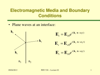
Boundary Conditions. Introductory FLUENT Training. Defining Boundary Conditions. To define a problem that results in a unique solution, you must specify information on the dependent (flow) variables at the domain boundaries Specify fluxes of mass, momentum, energy, etc. into the domain.

E N D
Boundary Conditions Introductory FLUENT Training
Defining Boundary Conditions • To define a problem that results in a unique solution, you must specify information on the dependent (flow) variables at the domain boundaries • Specify fluxes of mass, momentum, energy, etc. into the domain. • Defining boundary conditions involves: • Identifying the location of the boundaries (e.g., inlets, walls, symmetry) • Supplying information at the boundaries • The data required at a boundary depends upon the boundary condition type and the physical models employed. • You must be aware of the information that is required of the boundary condition and locate the boundaries where the information on the flow variables are known or can be reasonably approximated • Poorly defined boundary conditions can have a significant impact on your solution
1 2 3 1 Locating Boundaries: Example Air • Three possible approaches in locating inlet boundaries: 1Upstream of manifold • Can use uniform profile • Properly accounts for mixing • Non-premixed reaction models • Requires more cells 2Nozzle inlet plane • Non-premixed reaction models • Requires accurate profile data 3Nozzle outlet plane • Premixed reaction model • Requires accurate profile Combustor Wall Nozzle Manifold box Fuel
2 1 General Guidelines • General guidelines: • If possible, select boundary location and shape such that flow either goes in or out. • Not necessary, but will typically observe better convergence. • Should not observe large gradients in direction normal to boundary. • Indicates incorrect set-up. • Minimize grid skewness near the boundary. • Otherwise it would introduce error early in calculation. Upper pressure boundary modified to ensure that flow always enters domain.
outlet orifice wall plate plate-shadow inlet Available Boundary Condition Types • External faces • General – pressure inlet, pressure outlet • Incompressible – velocity inlet, outflow • Compressible – mass flow inlet, pressure far-field, mass flow outlet • Other – wall, symmetry, axis, periodic • Special – inlet vent, outlet vent, intake fan, exhaust fan • Cell zones • Fluid • Solid • Porous media • Heat exchanger • Internal faces • Fan, interior, porous jump, radiator, wall
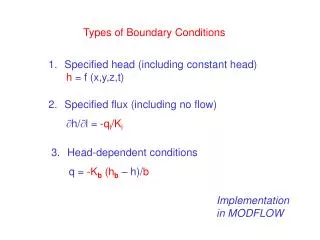
Changing Boundary Condition Types • Zones and zone types are initially defined in pre-processor. • To change zone type for a particular zone • Choose the zone name in Zone list. • Can also select boundary zone using right mouse button in the grid display. • Select new zone type in the Type list. Define Boundary Conditions…
Setting Boundary Condition Data • Explicitly assign data in BC panels. • To set boundary conditions for particular zone: • Choose the zone name in Zone list. • Click Set... button • Boundary condition data can be copied from one zone to another. • Boundary condition data can be stored and retrieved from a file using TUI commands: /file/write-bc /file/read-bc • Boundary conditions can also be defined by UDFs and profiles. • Profiles can be generated by: • Writing a profile from another CFD simulation • Creating an appropriately formatted text file with boundary condition data.
Velocity Inlet • Velocity Specification Method • Magnitude, Normal to Boundary • Components • Magnitude and Direction • Velocity profile is uniform by default • Intended for incompressible flows. • Static pressure adjusts to accommodate the prescribed velocity distribution. • Total (stagnation) properties of the flow also vary. • Using velocity inlets in compressible flows can lead to non-physical results. • Can be used as a “velocity outlet” by specifying negative velocity. • You must ensure that mass conservation is satisfied if multiple inlets are used.
Pressure Inlet • Gauge Total Pressure • Defines energy to drive flow. • Doubles as back pressure (static gauge) for cases where backflow occurs. • Direction of back flow determined from interior solution. • Supersonic/Initial Gauge Pressure • Static pressure where flow is locally supersonic; ignored if subsonic • This pressure will be used if the flow field is initialized from this boundary. • Total Temperature (Thermal tab) • Used as the static temperature for incompressible flow. • Inlet flow direction Incompressible flows: Compressible flows:
Pressure Inlet • Note that gauge pressure inputs are required. • Operating pressure level may sometimes affect solution accuracy (when pressure fluctuations are relatively small). • To set the operating pressure: • Suitable for compressible and incompressible flows. • Pressure inlet boundary is treated as loss-free transition from stagnation to inlet conditions. • FLUENT calculates static pressure and velocity at inlet • Mass flux through boundary varies depending on interior solution and specified flow direction. • Can be used as a “free” boundary in an external or unconfined flow. Define Operating Conditions…
Mass Flow Inlet • Required information • Mass Flow Rate or Mass Flux • Mass Flow Rate implies uniform mass flux. • Mass Flux can be defined using profile or UDF. • Supersonic/Initial Gauge Pressure • Static pressure where flow is locally supersonic; ignored if subsonic • Will be used if flow field is initialized from this boundary. • Total Temperature (on Thermal tab) • Used as static temperature for incompressible flow. • Direction Specification Method • Mass flow inlets are intended for compressible flows; however, they can be used for incompressible flows. • Total pressure adjusts to accommodate mass flow inputs. • More difficult to converge than pressure inlet.
Pressure Outlet • Required information • Gauge Pressure (static) • Interpreted as static pressure ofenvironment into which flow exhausts. • Radial equilibrium pressure distributionoption available • Doubles as inlet pressure (total gauge)for cases where backflow occurs • Backflow quantities • Can occur at pressure outlet eitherduring iterations or as part of final solution. • Backflow Direction Specification Method • Backflow boundary data must be set forall transport variables. • Convergence difficulties can be reduced by providing realistic backflow quantities • Suitable for compressible and incompressible flows • Specified pressure is ignored if flow is locally supersonic at the outlet • Can be used as a “free” boundary in an external or unconfined flow • For ideal gas (compressible) flow, non-reflecting outlet boundary conditions (NRBC) are available
Outflow • No pressure or velocity information isrequired. • Data at exit plane is extrapolated frominterior. • Mass balance correction is applied atboundary. • Flow exiting outflow boundary exhibits zero normal diffusive flux for all flow variables. • Appropriate where the exit flow is fully developed. • The outflow boundary is intended for use with incompressible flows. • Cannot be used with a pressure inlet boundary (must use velocity-inlet). • Combination does not uniquely set pressure gradient over whole domain. • Cannot be used for unsteady flows with variable density. • Poor rate of convergence when backflow occurs during iterations. • Cannot be used if backflow is expected in the final solution.
pressure-outlet (ps)1 velocity-inlet (V, T0) OR pressure-inlet (p0, T0) pressure-outlet (ps)2 outflow (FRW1) velocity-inlet (V, T0) outflow (FRW2) Modeling Multiple Exits • Flows with multiple exits can be modeled using pressure outlet or outflow boundaries. • Pressure outlets • Outflow: • Mass flow rate fraction determined from Flow Rate Weighting by • FRW set to 1 by default (implying equal flow rates) • Static pressure varies among exits to accommodate flow distribution.
Other Inlet / Outlet Boundary Conditions • Pressure Far Field • Used to model free-stream compressible flow at infinity, with prescribed static conditions and the free-stream Mach number. • Available only when density is calculated using the ideal gas law. • Target Mass Flow Rate option for pressure outlets (not available for the multiphase models) • Provides the ability to fix the mass flow rate on a pressure outlet (either constant or via UDF hook) • Options to choose iteration method in TUI • Exhaust Fan / Outlet Vent • Models an external exhaust fan or outlet vent with specified pressure rise / loss coefficient and ambient (discharge) pressure and temperature. • Inlet Vent / Intake Fan • Models an inlet vent / external intake fan with specified loss coefficient / pressure rise, flow direction, and ambient (inlet) pressure and temperature. • Inlet boundary conditions for large-eddy / detached-eddy simulations are covered in the Turbulence Modeling lecture.
Wall Boundaries • Used to bound fluid and solidregions. • In viscous flows, no-slipcondition enforced at walls. • Tangential fluid velocity equalto wall velocity. • Zero normal velocitycomponent • Shear stress can also bespecified. • Thermal boundary conditions • Several types available • Wall material and thickness can be defined for 1D or shell conduction heat transfer calculations (details will be discussed in the Heat Transfer lecture). • Wall roughness can be defined for turbulent flows. • Wall shear stress and heat transfer based on local flow field. • Translational or rotational velocity can be assigned to wall boundaries.
Symmetry and Axis Boundaries • Symmetry Boundary • Used to reduce computational effort in problem. • No inputs are required. • Flow field and geometry must be symmetric: • Zero normal velocity at symmetry plane • Zero normal gradients of all variables at symmetry plane • Must take care to correctly define symmetry boundary locations. • Can be used to model slip walls in viscous flow • Axis Boundary • Used at the center line for axisymmetric problems. • No user inputs required. • Must coincide with thepositive x direction! symmetry planes axis
Periodic Boundaries • Used to reduce the overall mesh size. • Flow field and geometry must contain either rotational or translational periodicity. • Rotational periodicity • P = 0 across periodic planes. • Axis of rotation must be defined in fluid zone. • Translational periodicity • P can be finite across periodic planes. • Models fully developed conditions. • Specify either mean P per period or net mass flow rate. • Periodic boundaries defined in GAMBIT are translational. Rotationally periodic planes Flow Translationally periodic planes 2D Tube Heat Exchanger
Cell Zones – Fluid • A fluid cell zone is a group of cells for which all active equations are solved. • Fluid material selection is required. • For multiple species or multiphase flows, the material is not shown. Instead, the fluid zone consists of the mixture of the phases. • Optional inputs allow specification of source terms. • Mass, momentum, energy, UDS, etc. • Define the fluid zone as laminar flow region if trying to model transitional flow. • Can define the zone as porous media. • Define axis of rotation for rotationally periodic flows. • Can define motion of the fluid zone.
Porous Media Conditions • Porous zone modeled as special type of fluid zone. • Enable Porous Zone option in the Fluid panel. • Pressure loss in flow determined via user inputsof resistance coefficients to lumped parametermodel • Used to model flow through porous media and other “distributed” resistances.For example, • Packed beds • Filter papers • Perforated plates • Flow distributors • Tube banks
Cell Zones – Solid • A solid zone is a group of cells for which only heat conduction problem solved • No flow equations are solved. • Material being treated as solid may actually be fluid, but it is assumed that no convection occurs. • Only required input is the material name defined in the materials (solid) panel. • Optional inputs allow you to set volumetric heat generation rate (heat source). • Need to specify rotation axis if rotationally periodic boundaries adjacent to solid zone. • Can define motion for solid zone
Internal Face Boundaries • Defined on the cell faces only: • Thickness of these internal faces is zero • These internal faces provide means of introducing step changes in flow properties. • Used to implement various physical models including: • Fans • Radiators • Porous-jump models • Preferable over porous media for its better convergence behavior. • Interior walls
Summary • Zones are used to assign boundary conditions. • Wide range of boundary conditions permit flow to enter and exit the solution domain. • Wall boundary conditions are used to bound fluid and solid regions. • Periodic boundaries are used to reduce computational effort. • Internal cell zones are used to specify fluid, solid, and porous regions and heat-exchanger models. • Internal face boundaries provide way to introduce step-changes in flow properties.