Download
1 / 23
230 likes | 365 Views
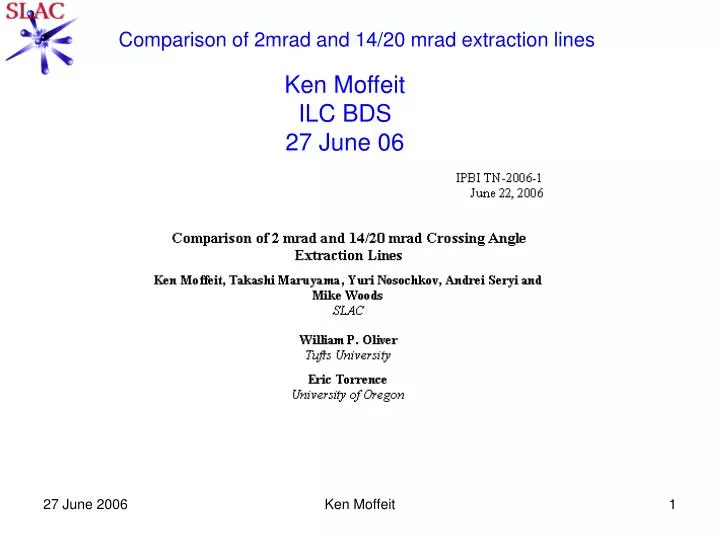
Comparison of 2mrad and 14/20 mrad extraction lines. Ken Moffeit ILC BDS 27 June 06. BDS Layout. 2 mrad. 14/20 mrad. 14/20 mrad Extraction Line. 2 mrad Extraction Line. The extraction line transport is simulated using the program GEANT.

E N D
Comparison of 2mrad and 14/20 mrad extraction lines Ken Moffeit ILC BDS 27 June 06 Ken Moffeit
BDS Layout 2 mrad 14/20 mrad Ken Moffeit
14/20 mrad Extraction Line Ken Moffeit
2 mrad Extraction Line Ken Moffeit
The extraction line transport is simulated using the program GEANT. Disrupted beam events were taken from files prepared by Andrei Seryi. For these studies files: cs11 corresponds to a normal ILC beam (mean energy 244.3 GeV and RMS 10.84 GeV) cs13 with parameters set for large-y (mean energy 243.1 GeV and RMS 11.14 GeV). cs13 dy = 4nm gives large-y parameter data sets with the centroid of the beams missing by 4nm in the vertical (mean energy 242.2 GeV and RMS 12.05 GeV) cs13 dx =200nm has beams missing by 200nm in the horizontal (mean energy 243.3 GeV and RMS 10.94 GeV) Ken Moffeit
Spin Precession Change in spin direction for various bend angles and the projection of the longitudinal polarization. Electron beam energy is 250 GeV. Ken Moffeit
2mrad x vs y +/-100 mm Ken Moffeit
2mrad Extraction Line: Beam accepted and polarization projection for various +- 100 micron selections about the x value of the beam at the Compton IP. In each case abs(y+2.0cm)<100 microns and abs(x-137.45). Ken Moffeit
20mrad Extraction Line with 2.019<y<-1.999cm and abs(x)<0.01cm 2 mrad Extraction Line with abs(y+2)<0.01cm and abs(x-137.45)<0.01cm Ken Moffeit
Beam Losses from the e+e- IR to the Compton Detector Plane 20 mrad Crossing Angle Extraction Line 2 mrad Crossing Angle Extraction Line Ken Moffeit
Beam Losses Beam losses were further studied by using a file with the tails of the disrupted beam having events with energy less than 0.65 of the beam energy or the angle greater than 0.5 mrad: http://www.slac.stanford.edu/~seryi/ILC_new_gp_files/cs11_hs/tail1_lt_0_65E0_or_gt_500urad.dat Ken Moffeit
2mrad extraction line Only 5899 of the 10,503 particles continue to the Compton Detector plane. This represents a loss of 2.62*10-4 of the 17.59 million original beam tracks. Estimate ~50 photons/cm2 are in the region of the Cherenkov counter cells for each bunch of 2*1010 electrons Only ~20% above 10 MeV Can reduce by local shielding of Cherenkov Detector Compton Signal ~650 backscattered electrons per GeV or >1000 per 1cm cell Ken Moffeit
Synchrotron Radiation Ken Moffeit
Conclusions • The 20 mrad extraction line has: • Core of beam within +-100microns has between 32 and 48% of the beam. • The polarization projection is 99.75 to 99.85% at the Compton IP. • No beam losses from e+e- IR to Compton detector plane out of 17.6 million beam tracks. • Beam energy loss due to synchrotron radiation to the middle of energy chicane (z=59.7 m) is only ~110 MeV and does not show variation with beam conditions. • The collimator at z=164.25 meters needs to be designed. It absorbs the synchrotron radiation above the 0.75 mrad beam stay clear allowing the Cherenkov detector to begin at y~14 cm. Ken Moffeit
The 2 mrad extraction line has: • There are large beam losses between e+e- IR and Compton detector plane (>2.6*10-4 are lost) giving secondary backgrounds of mainly photons in the region of the Cherenkov Detector. • A small percentage of beam is hit by laser spot +-100 microns (~15%) at the Compton IP and results in low Compton luminosity. • There are large beam energy losses (~850 MeV) due to synchrotron radiation between IR and the center of the energy chicane at z=198.82 meters. • Synchrotron radiation at Cherenkov Detector is favorable. The detector only sees the synchrotron radiation from the magnets of the polarimeter chicane, and this is contained between -9 and +2 cm. The first cell of the Cherenkov Detector starts at +10 cm. Ken Moffeit