Download
1 / 10
100 likes | 282 Views
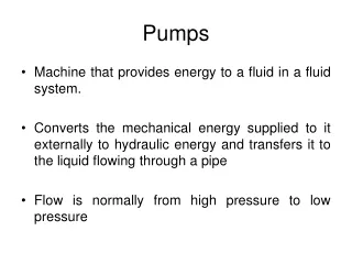
The APP pumps are designed for SWRO in land-based and marine applications, offering the highest efficiency rates in the industry. For small and medium-sized desalination plants. <br>

E N D
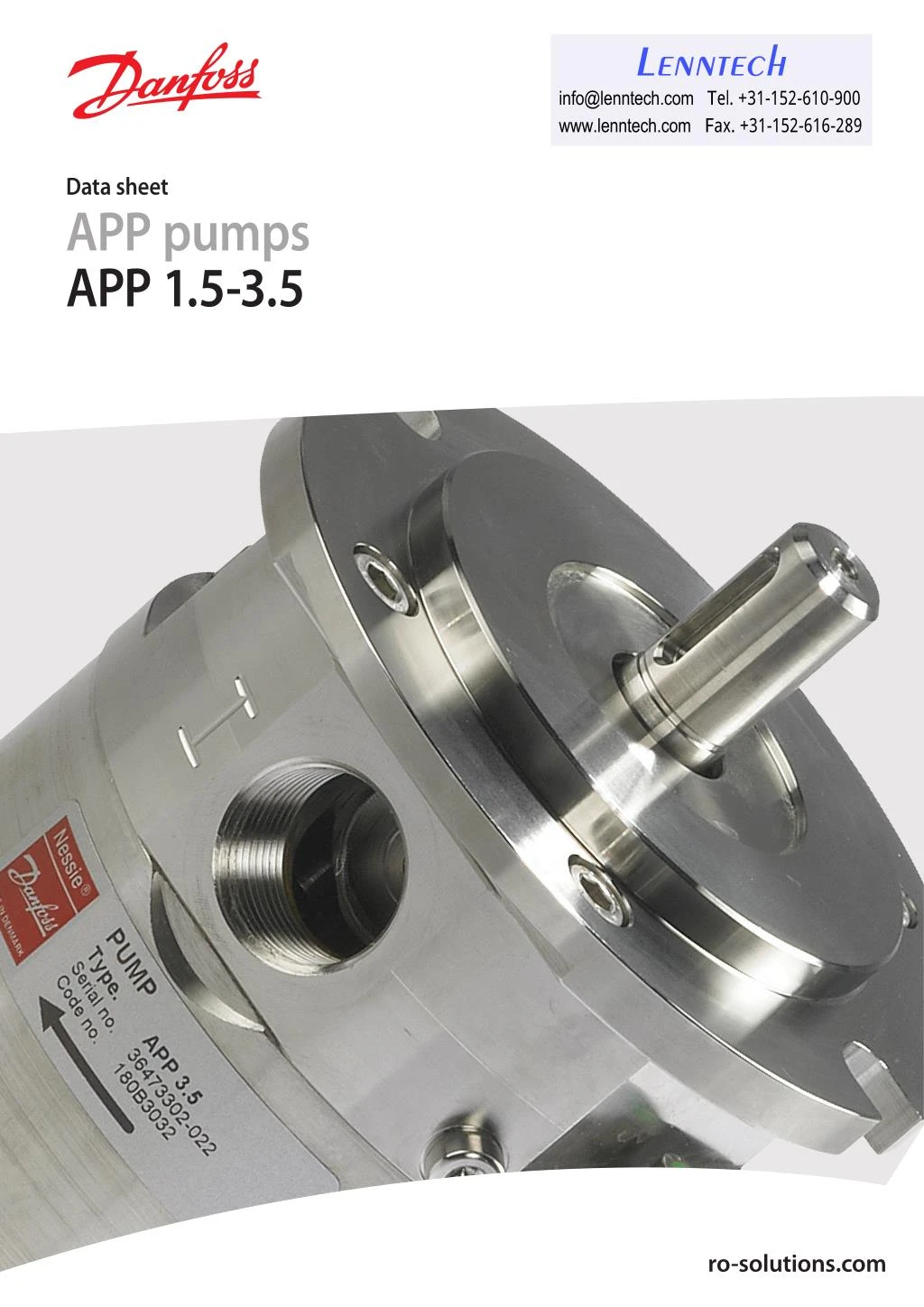
Lenntech info@lenntech.com Tel. +31-152-610-900 www.lenntech.com Fax. +31-152-616-289 Data sheet APP pumps APP 1.5-3.5 ro-solutions.com
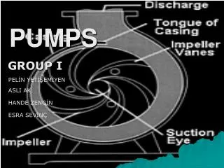
Data sheet APP pumps - APP 1.5-3.5 Table of Contents 1. General information. . . . . . . . . . . . . . . . . . . . . . . . . . . . . . . . . . . . . . . . . . . . . . . . . . . . . . . . . . . . . . . . . . . . .2 2. Benefits. . . . . . . . . . . . . . . . . . . . . . . . . . . . . . . . . . . . . . . . . . . . . . . . . . . . . . . . . . . . . . . . . . . . . . . . . . . . . . . . .3 3. Technical data . . . . . . . . . . . . . . . . . . . . . . . . . . . . . . . . . . . . . . . . . . . . . . . . . . . . . . . . . . . . . . . . . . . . . . . . . .3 4. Flushing valve. . . . . . . . . . . . . . . . . . . . . . . . . . . . . . . . . . . . . . . . . . . . . . . . . . . . . . . . . . . . . . . . . . . . . . . . . . .4 5. Flow at different rpm. . . . . . . . . . . . . . . . . . . . . . . . . . . . . . . . . . . . . . . . . . . . . . . . . . . . . . . . . . . . . . . . . . . .4 6. Power requirements . . . . . . . . . . . . . . . . . . . . . . . . . . . . . . . . . . . . . . . . . . . . . . . . . . . . . . . . . . . . . . . . . . . .5 7. 7.1 7.2 Temperature and corrosion. . . . . . . . . . . . . . . . . . . . . . . . . . . . . . . . . . . . . . . . . . . . . . . . . . . . . . . . . . . . . .5 Operation. . . . . . . . . . . . . . . . . . . . . . . . . . . . . . . . . . . . . . . . . . . . . . . . . . . . . . . . . . . . . . . . . . . . . . . . . . . . . . .5 Storage. . . . . . . . . . . . . . . . . . . . . . . . . . . . . . . . . . . . . . . . . . . . . . . . . . . . . . . . . . . . . . . . . . . . . . . . . . . . . . . . .6 8. Noise level. . . . . . . . . . . . . . . . . . . . . . . . . . . . . . . . . . . . . . . . . . . . . . . . . . . . . . . . . . . . . . . . . . . . . . . . . . . . . .6 9. Filtration. . . . . . . . . . . . . . . . . . . . . . . . . . . . . . . . . . . . . . . . . . . . . . . . . . . . . . . . . . . . . . . . . . . . . . . . . . . . . . . .6 10. 10.1 10.2 Dimensions. . . . . . . . . . . . . . . . . . . . . . . . . . . . . . . . . . . . . . . . . . . . . . . . . . . . . . . . . . . . . . . . . . . . . . . . . . . . .7 Pump. . . . . . . . . . . . . . . . . . . . . . . . . . . . . . . . . . . . . . . . . . . . . . . . . . . . . . . . . . . . . . . . . . . . . . . . . . . . . . . . . . .7 Complete unit . . . . . . . . . . . . . . . . . . . . . . . . . . . . . . . . . . . . . . . . . . . . . . . . . . . . . . . . . . . . . . . . . . . . . . . . . .8 11. 11.1 11.2 11.3 Installation. . . . . . . . . . . . . . . . . . . . . . . . . . . . . . . . . . . . . . . . . . . . . . . . . . . . . . . . . . . . . . . . . . . . . . . . . . . . . .8 Mounting. . . . . . . . . . . . . . . . . . . . . . . . . . . . . . . . . . . . . . . . . . . . . . . . . . . . . . . . . . . . . . . . . . . . . . . . . . . . . . .8 Open-ended system with direct water supply. . . . . . . . . . . . . . . . . . . . . . . . . . . . . . . . . . . . . . . . . . . .9 RO system with APP pump . . . . . . . . . . . . . . . . . . . . . . . . . . . . . . . . . . . . . . . . . . . . . . . . . . . . . . . . . . . . . .9 DATA SHEET Water Pumps APP1.5 - 3.5 12. 12.1 12.2 12.3 Service . . . . . . . . . . . . . . . . . . . . . . . . . . . . . . . . . . . . . . . . . . . . . . . . . . . . . . . . . . . . . . . . . . . . . . . . . . . . . . . .10 Warranty. . . . . . . . . . . . . . . . . . . . . . . . . . . . . . . . . . . . . . . . . . . . . . . . . . . . . . . . . . . . . . . . . . . . . . . . . . . . . . .10 Maintenance. . . . . . . . . . . . . . . . . . . . . . . . . . . . . . . . . . . . . . . . . . . . . . . . . . . . . . . . . . . . . . . . . . . . . . . . . . .10 Repair . . . . . . . . . . . . . . . . . . . . . . . . . . . . . . . . . . . . . . . . . . . . . . . . . . . . . . . . . . . . . . . . . . . . . . . . . . . . . . . . .10 1. General information 1. General information APP 1.5, APP 1.8, APP 2.2, APP 2.5, APP 3.0 and APP 3.5 pumps are designed to supply low viscosity and corrosive fluids under high pressure, e.g. in seawater reverse osmosis filtration applications and for high-pressure saltwater pumping. All parts included in the pumps are designed to provide long service life, i.e. long service life with a constantly high efficiency and minimum of service required. The pumps are fixed displacement pumps in which the flow is proportional to the number of revolutions of the input shaft and the pump displacement, regardless of any counter- pressure. The pumps are based on the axial piston principle enabling a very light and compact design. The design ensures that lubrication of the moving parts in the pumps is provided by the fluid itself. No oil lubrication is thus required. minimum of service required. APP1.5, APP1.8, APP2.2, APP2.5, APP3.0 and APP3.5 pumps are designed to supply low viscosity and corrosive fl uids under high pressure, eg in seawater reverse osmosis fi ltration applications and for high-pressure salt water pumping. The pumps are based on the axial piston principle enabling a very light and compact design. The design ensures that lubrication of the moving parts in the pumps is provided by the fl uid itself. No oil lubrication is thus required. The pumps are supplied with an integrated flushing valve that allows the salt water to flow from inlet to the outlet, when the pump is not running. All parts included in the pumps are designed to provide long service life, ie long service life with a constantly high effi ciency and The pumps are fi xed displacement pumps in which the fl ow is proportional to the number of revolutions of the input shaft and the pump displacement, regardless of any counter-pressure. The pumps are supplied with an integrated fl ushing valve that allows the salt water to fl ow from inlet to the outlet, when the pump is not running. 2 1 6 7 114 12 1: Shaft sealing 2: Mounting flange 3: Retaining ring 4: Piston/shoe 5: Valve plate 6: Swash plate 7: Cylinder barrel 8: Spring 9: Port plate 10: Connecting flange 11: Housing with bearing 12: Flushing valve 1: 2: 3: 4: 5: 6: 7: 8: 9: 10: 11: 12: Shaft sealing Mounting fl ange Retaining ring Piston/shoe Valve plate Swash plate Cylinder barrel Spring Port plate Connecting fl ange Housing with bearing Flushing valve 5 8 9 3 11 10 2. • Benefi ts One of the smallest and lightest pumps on the market. Can be powered by a combustion engine. Long service life / No preventive maintenance required in the warranty period. Generates insignifi cant pulsations in the high-pressure line. No oil lubricant required. Integrated fl ushing valve All parts of the pump are made of high corrosion resistant materials eg Duplex (EN1.4462/UNS S31803-S32205) and Super-duplex (EN1.4410/UNS S32750) stainless steel and carbon reinforced PEEK High effi ciency 2 521B0850 / DKCFN.PD.013.FA6.02 / 09.2012 • • • • • • • 521B0850 DKCFN.PD.013.FA6.02 03-2010
Data sheet APP pumps - APP 1.5-3.5 2. Benefits • One of the smallest and lightest pumps on the market. Can be powered by a combustion engine. Long service life / No preventive maintenance required in the warranty period. Generates insignificant pulsations in the high-pressure line. • • • No oil lubricant required. Integrated flushing valve All parts of the pump are made of high corrosion resistant materials; e.g. Duplex (EN1.4462/UNS S31803-S32205) and Super Duplex (EN1.4410/UNS S32750), stainless steel and carbon reinforced PEEK High efficiency • • • • 3. Technical data APP pumps APP 1.5 APP 1.8 APP 2.2 APP 2.5 APP 3.0 APP 3.5 Code number 180B3043 180B3044 180B3045 180B3046 180B3030 180B3032 Geometric displacement cm3 9.3 10 12.5 15.3 17.7 20.5 in3/rpm 0.56 0.61 0.76 0.93 1.08 1.25 Rated flow (3000 rpm) 1) m3/h 1.5 1.7 2.1 2.6 3.0 3.5 gpm 6.6 7.5 9.2 11.4 13.2 15.4 Outlet min. pressure 2) bar 20 20 20 20 20 20 psi 290 290 290 290 290 290 Outlet max. pressure, continuous 3) bar 80 80 80 80 80 80 psi 1160 1160 1160 1160 1160 1160 Outlet max. pressure, intermittent 4) bar 100 100 100 100 100 100 psi 1450 1450 1450 1450 1450 1450 Inlet min. pressure bar 0.5 0.5 0.5 5) 0.5 0.5 5) 0.5 psi 7.3 7.3 7.3 7.3 7.3 7.3 Inlet max. pressure, continuous bar 5 5 5 5 5 5 psi 72.5 72.5 72.5 72.5 72.5 72.5 Inlet max. pressure, peak bar 10 10 10 10 10 10 psi 145 145 145 145 145 145 Max. speed continuous rpm 3450 3450 3450 5) 3000 3450 5) 3000 Min. speed continuous rpm 700 700 700 700 700 700 Power requirement at 80 bar and 3000 rpm kW 4.5 4.8 6.0 7.2 8.4 9.8 hp 6 6.3 7.9 9.6 11.3 13.1 Torque at 80 bar Nm 14,2 15.3 19 23 25.6 29.7 lbf-ft 10.5 11.3 14 17 18.8 21.9 Weight Kg 8.6 8.6 8.6 8.6 8.6 8.6 lb 17 17 17 17 17 17 Integrated flushing valve YES YES YES YES YES YES 1) Typical average flow at 80 bar (1160 psi). 2) For lower pressure, please contact Danfoss RO Sales Organization. 3) For higher pressure, please contact Danfoss RO Sales Organzation. 4) Intermittent pressure is acceptable for less than 10 seconds per minute. 5) For speeds above 3000 rpm the pump must be boosted at a pressure of 2-5 bar (29.0 - 72.5 psi). 3 521B0850 / DKCFN.PD.013.FA6.02 / 09.2012
3. Technical data APP pumps Code number APP1.5 180B3043 APP1.8 180B3044 180B3045 180B3046 180B3030 180B3032 APP2.2 APP2.5 APP3.0 APP3.5 cm3/rpm 9.3 (0.56) 10 12.5 (0.76) 15.3 (0.93) 17.7 (1.08) 20.5 (1.25) (in3/ rpm) m3/h (gpm) bar (psi) bar (psi) bar (psi) bar (psi) bar (psi) bar (psi) Geometric displacement (0.61) 1.5 (6.6) 20 (290) 80 (1160) 100 (1450) 0.5 (7.3) 5 (72.5) 10 (145) 1.7 (7.5) 20 (290) 80 (1160) 100 (1450) 0.5 (7.3) 5 (72.5) 10 (145) 2.1 (9.2) 20 (290) 80 (1160) 100 (1450) 0.5 5) (7.3) 5 (72.5) 10 (145) 3450 5) 2.6 (11.4) 20 (290) 80 (1160) 100 (1450) 0.5 (7.3) 5 (72.5) 10 (145) 3.0 (13.2) 20 (290) 80 (1160) 100 (1450) 0.5 5) (7.3) 5 (72.5) 10 (145) 3450 5) 3.5 (15.4) 20 (290) 80 (1160) 100 (1450) 0.5 (7.3) 5 (72.5) 10 (145) Rated fl ow (3000 rpm) 1) Outlet min. pressure 2) Outlet max. pressure, continuous 3) Outlet max. pressure, intermittent 4) Inlet min. pressure Inlet max. pressure, continuous Inlet max. pressure, peak Max. speed continuous rpm 3450 3450 3000 3000 Min. speed continuous rpm 700 700 700 700 700 700 Power requirement at 80 bar and 3000 rpm kW (hp) Nm 4.5 (6) 14,2 (10.5) 8.6 (17) 4.8 (6.3) 15.3 (11.3) 8.6 (17) 6.0 (7.9) 19 (14) 8.6 (17) 7.2 (9.6) 23 (17) 8.6 (17) 8.4 (11.3) 25.6 (18.8) 8.6 (17) 9.8 (13.1) 29.7 (21.9) 8.6 (17) Torque at 80 bar (lbf-ft) Kg (lb) Weight Integrated fl ushing valve YES YES YES YES YES YES Data sheet APP pumps - APP 1.5-3.5 1) Typical average fl ow at 80 bar (1160 psi). 2) For lower pressure, please contact Danfoss RO Sales Organization. 3) For higher pressure, please contact Danfoss RO Sales Organzation. 4) Intermittent pressure is acceptable for less than 10 seconds per minute. 5) For speeds above 3000 rpm the pump must be boosted at a pressure of 2-5 bar (29.0 - 72.5 psi). 4. Flushing valve The diagram shows pressure differences across the flushing valve: 4. Flushing valve APP1.5-3.5 flushing valve characteristic APP 1.5-3.5 flushing valve characteristic 20 20 18 18 16 16 14 14 12 12 Flow [l/min) Flow[l/min] 10 10 8 8 6 8 4 4 2 2 0 0 2 2 3 3 4 4 5 1 1 0 2 5 Pressure [bar] Pressure [bar] 2 DKCFN.PD.013.FA6.02 521B0850 5. Flow at different rpm Using the diagram shown below, it is easy to select the pump which fits the application best if the flow required and the rotation speed (rpm) of the pump are known. Using the diagram shown below, it is easy to select the pump which fi ts the application best if the fl ow required and the rotation speed (rpm) of the pump are known. 5. Flow at diff erent rpm 4 APP3.5 APP3.0 3,5 APP2.5 3 APP2.2 2,5 m³/h APP1.8 2 APP1.5 1,5 1 0,5 0 0 500 1000 1500 2000 2500 3000 3500 rpm Furthermore, this diagram shows that the fl ow can be changed by changing the rotation speed of the pump. The fl ow/rpm ratio is constant, and the “required “ fl ow can be obtained by changing the rotation speed to a corresponding value. Thus, the required rpm can be determined as: Required fl ow × Rated rpm Required rpm = Rated fl ow Furthermore, this diagram shows that the flow can be controlled by changing the rotation speed of the pump. The flow/rpm ratio is constant, and the “required“ flow can be obtained by changing the rotation speed to a corresponding value. Thus, the required rpm can be determined as: l/min m3/h 6. Power requirements Pump model Flow Pressure rpm Calc. factor 60 bar 70 bar 80 bar gpm 870 psi 1015 psi 1160 psi APP1.5 25.11 1.51 6.63 3.21 kW 3.75 kW 4.29 kW 2890 468.6 Required rpm = APP2.2 Required flow × Rated rpm 1.61 APP1.5 30.17 1.81 7.97 3.86 kW 4.51 kW 5.15 kW 3470 468.6 APP1.8 26.78 7.07 3.43 kW 4.00 kW 4.57 kW 2890 463.2 Rated flow APP1.8 32.18 1.93 8.50 4.12 kW 4.81 kW 5.49 kW 3470 463.2 33.48 2.01 8.84 4.29 kW 5.00 kW 5.71 kW 2900 468.6 APP2.2 40.22 2.41 10.63 5.15 kW 6.01 kW 6.87 kW 3480 468.6 APP2.5 41.94 2.52 11.08 5.07 kW 5.92 kW 6.77 kW 2900 484.8 4 521B0850 / DKCFN.PD.013.FA6.02 / 09.2012 APP3.0 48.2 2.9 12.7 6.2 kW 7.2 kW 8.2 kW 2930 470.0 APP3.5 56.0 3.4 14.8 7.2 kW 8.4 kW 9.6 kW 2930 470.0 The power requirements can be determined using one of the following guiding equations: Required power = l/min × bar Calc. factor 16.7 × m3/h × bar Calc. factor 0.26 × gpm × psi Calc. factor [kW] or [kW] or [kW] 1 hp = 0.75 kW 1 kW = 1.34 hp 1 gpm = 3.79 l/min 1 l/min = 0.26 gpm 1 m3/h = 4.40 gpm 1 gpm = 0.23 m3/h 521B0850 DKCFN.PD.013.FA6.02 3
Data sheet APP pumps - APP 1.5-3.5 6. Power requirements Pump model Flow Pressure rpm Calc. factor 60 bar 70 bar 80 bar l/min m3/h gpm 870 psi 1015 psi 1160 psi APP 1.5 25.11 1.51 6.63 3.21 kW 3.75 kW 4.29 kW 2890 468.6 APP 1.5 30.17 1.81 7.97 3.86 kW 4.51 kW 5.15 kW 3470 468.6 APP 1.8 26.78 1.61 7.07 3.43 kW 4.00 kW 4.57 kW 2890 463.2 APP 1.8 32.18 1.93 8.50 4.12 kW 4.81 kW 5.49 kW 3470 463.2 APP 2.2 33.48 2.01 8.84 4.29 kW 5.00 kW 5.71 kW 2900 468.6 APP 2.2 40.22 2.41 10.63 5.15 kW 6.01 kW 6.87 kW 3480 468.6 APP 2.5 41.94 2.52 11.08 5.07 kW 5.92 kW 6.77 kW 2900 484.8 APP 3.0 48.2 2.9 12.7 6.2 kW 7.2 kW 8.2 kW 2930 470.0 APP 3.5 56.0 3.4 14.8 7.2 kW 8.4 kW 9.6 kW 2930 470.0 The power requirements can be determined using one of the following guiding equations: Required power = l/min × bar 16.7 × m3/h × bar 0.26 × gpm × psi [kW] or [kW] or [kW] Calc. factor Calc. factor Calc. factor 1 hp 1 kW 1 gpm = 3.79 l/min 1 l/min = 0.26 gpm 1 m3/h = 4.40 gpm 1 gpm = 0.23 m3/h = 0.75 kW = 1.34 hp 7. Temperature and corrosion 7.1 Operation Fluid temperature: +2° C to +50° C (+35.6° F to 122° F) dependent on the NaCl concentration Ambient temperature: +2° C to +50° C (+35.6° F to 122° F) The chart below illustrates the corrosive resistance of different types of stainless steel related to NaCl concentration and temperature. If the water pump is operated at high salinity, always flush the water pump with fresh water at operation stop in order to minimize the risk of crevice corrosion. All critical parts of the APP water pump is made of Super Duplex. 5 521B0850 / DKCFN.PD.013.FA6.02 / 09.2012
Data sheet APP pumps - APP 1.5-3.5 7.2 Storage Frost protection is required at temperatures below 2°C. Danfoss recommends to use DOW- FROST from DOW Chemical Company or Chilsafe mono propylene glycol from Arco Chemical Company. Storage temperature: -40°C to +70°C (+40°F to 158°F) provided that the pump is drained of fluid and stored ”plugged”. 8. Noise level The table indicates the approximate noise level in dB(A) measured at a distance of 1 m from the pump in a reverberation room. Type 60 bar (870 psi) 1500 rpm 60 bar (870 psi) 3000 rpm APP 1.5 75 76 APP 1.8 75 76 APP 2.2 75 76 APP 2.5 76 77 APP 3.0 72 77 APP 3.5 72 77 The noise level is influenced by: • The speed of the pump, high rpm create more noise than low rpm • Rigid mounting of the pump generates more noise than flexible mounting • Pipe mounting direct to the pump increases the noise level compared to a flexible hose Generally, noise will be reduced if speed is reduced and vice versa. Use flexible hoses in order to minimize vibrations and noise. Since the pump is typically mounted on a bell housing or frame, the noise level must be determined for the complete unit (system). It is therefore very important that the motor/ pump unit is mounted correctly on a frame with antivibration isolation to minimize vibrations and noise. 9. Filtration As water has very low viscosity, the APP pumps have been designed with very narrow clearance in order to control internal leakage rates and improve component performance. Therefore it is important that the inlet water is filtered properly to minimize the wear of the pump. the filter, 50,000 particles pass through it compared to only 20 particles in a filter with an efficiency of 99.98%. For more information on the importance of proper filtration, please consult our publication “Filtration” (code number 521B1009), which also will provide you with an explanation of filtration definitions and a guidance on how to select the right filter. The main filter must have a filtration efficiency of 99.98% at 10 μm. We recommend to use precision depth filter cartridges rated 10μm abs. ß10>5000 (equivalent to a filtration efficiency of 99.98%). Bag filters and string wound filter cartridges typically have only 50% filtration efficiency. This means that for each 100,000 particles reaching 6 521B0850 / DKCFN.PD.013.FA6.02 / 09.2012
Data sheet APP pumps - APP 1.5-3.5 10. Dimensions 10.1 Pump Description APP 1.5 - APP 3.5 A Port position mm 21.0 in 0.83 B Port position mm 21.0 in 0.83 C mm Ø 105 in 4.1 D mm 166 in 6.5 E Parallel key, DIN 6885 mm 5 × 5 × 20 in 0.20 × 0.20 × 0.78 F Bleeding M6, Hexagon AF = 5 mm I Inlet connection BSP G¾”; 15 (0.59) deep O Outlet connection BSP G¾”; 17 (0.67) deep Pump mounting flange SAE A 2 7 521B0850 / DKCFN.PD.013.FA6.02 / 09.2012
Data sheet APP pumps - APP 1.5-3.5 10.2 Complete unit Pump A (mm) B (mm) C (mm) D (mm) E (mm) F (mm) G (mm) H (mm) IEC Electric motor APP 1.5 250 260 100 160 140 325 120 166 3.0 kW, IEC 100L-2 APP 1.8 250 290 112 190 140 340 120 166 4.0 kW, IEC 112M-2 APP 2.2 300 338 132 216 140 403 144 166 5.5 kW, IEC 132S1-2 APP 2.5 300 338 132 216 178 403 144 166 7.5 kW, IEC 132S2-2 APP 3.0 350 422 160 254 210 505 188 166 11 kW, IEC 160M1-2 APP 3.5 350 422 160 254 210 505 188 166 11 kW, IEC 160M1-2 11. Installation 11.1 Mounting The figure below illustrates how to mount the pump and connect it to electric motor/combus- tion engine. To ensure easy mounting of the flexible coupling without using tools, the tolerances must be dimensioned accordingly. Note: Any axial and/or radial loads on the shaft must be avoided. A: B: C: Flexible coupling Bell housing Motor shaft If alternative mounting is required, please contact Danfoss Sales Organization for further information. The pump should be connected to the rest of the plant with flexible hoses. Min. 5 mm A B C 8 521B0850 / DKCFN.PD.013.FA6.02 / 09.2012
Data sheet APP pumps - APP 1.5-3.5 11.2 Open-ended system with direct water supply In order to eliminate the risk of cavitation, a positive inlet pressure is always to be main- tained. Please see technical data (part 3.) for specific pressure values. 1. Place the filter (1) in the water supply line in front of the pump. 2. Place a monitoring pressure switch (2) - set at min. inlet pressure - between filter and pump inlet. The monitoring switch must stop the pump at pressures lower than min. inlet pressure. Please see technical data (part 3.) for specific pressure values. 11.3 RO system with APP pump 1. Dimension the inlet line to obtain mini- mum pressure loss (large flow, minimum pipe length, minimum number of bends/ connections and fittings with small pressure losses). 6. For easy system bleeding and flushing, a bypass non-return valve (6) is integrated in the APP pump. 7. A non-return valve (7) in outlet can be installed in order to avoid backspin of the pump. The volume of water in the membrane vessel works as an accumulator and will send flow backwards in case of the pump stops momentarily. 2. Place an inlet filter (1) in front of the APP pump (2). Please consult section 9, “Filtration” for guidance on how to select the right filter. Thoroughly clean pipes and flush system prior to start-up. 8. A safety valve (8) can be installed in order to avoid system damage as the Danfoss APP pump creates pressure and flow immediately after start-up, regardless of any counter-pressure. 3. Place a monitoring pressure switch (3) set at min. inlet pressure between filter and pump inlet. The monitoring switch must stop the pump at pressures lower than minimum pressure. 4. Use flexible hoses (4) to minimize vibrations and noise. 5. In order to eliminate the risk of damage and cavitation, a positive pressure at the inlet (5) is always to be maintained at min. inlet pressure and max. inlet pressure. 9 521B0850 / DKCFN.PD.013.FA6.02 / 09.2012
Data sheet APP pumps - APP 1.5-3.5 12. Service 12.1 Warranty Danfoss APP pumps are designed for long operation, low maintenance and reduced lifecycle costs. 12.3 Repair In case of irregular function of the APP, please contact the Danfoss RO Solutions Sales Organisa- tion. Provided that the pump has been running according to the Danfoss specifications, Danfoss guarantees 8,000 hours service-free operation, however, max. 18 months from date of produc- tion. If Danfoss recommendations concerning system-design are not followed, it will strongly influence the life of the APP pumps. 12.2 Maintenance After 8,000 hours of operation it is strongly recommended to inspect the pump and change any worn parts, e.g. pistons and shaft seal. This is done in order to prevent a potential breakdown of the pump. If the parts are not replaced, more frequent inspection is recommended according to our guidelines. Standstill The APP pumps are made of Duplex/Super Duplex materials with excellent corrosion properties. It is, however, always recommended to flush the pump with freshwater when the system is shut down. Lenntech info@lenntech.com Tel. +31-152-610-900 www.lenntech.com Fax. +31-152-616-289 Danfoss A/S High Pressure Pumps DK-6430 Nordborg Denmark Danfoss can accept no responsibility for possible errors in catalogues, brochures and other printed material. Danfoss reserves the right to alter its products without notice. This also applies to products already on order provided that such alterations can be made without subsequential changes being necessary in specifications already agreed. All trademarks in this material are property of the respective companies. Danfoss and the Danfoss logotype are trademarks of Danfoss A/S. All rights reserved. 10 521B0850 / DKCFN.PD.013.FA6.02 / 09.2012