Download
1 / 52
680 likes | 1.29k Views
Chemical Vapor Deposition (CVD). References : D.M. Dobkin and M.K. Zuraw, Principles of Chemical Vapor Deposition (Kluwer Academic Publishers, 2003) M. L. Hitchman and K. F. Jensen, Chemical Vapor Deposition (Academic Press, 1993)

E N D
Chemical Vapor Deposition (CVD) References : D.M. Dobkin and M.K. Zuraw, Principles of Chemical Vapor Deposition (Kluwer Academic Publishers, 2003) M. L. Hitchman and K. F. Jensen, Chemical Vapor Deposition (Academic Press, 1993) M. Ohring, The Materials Science of Thin Films (Academic Press, 1992) M.A. Herman, W. Richter and H. Sitter, Epitaxy: Physical Principles and Technical Implementation (Springer, 2004)
Chemical Vapor Deposition (CVD) Thin Film Deposition PVD CVD • CVD : Film species are supplied in the form of a precursor gas
Chemical Vapor Deposition (CVD) Horizontal: Barrel: Pancake: From Ohring, Fig. 4-13, p. 178
CVD Chemistry • Heterogeneous and homogeneous reactions From Herman, Fig. 8.3, p. 173 From Sze, Fig. 19, p. 323
Chemical Vapor Deposition (CVD) • All CVD systems consist of three steps: • gas transport into the chamber and to the substrate • 2) chemical reactions forming the film • aA(g) + bB(g) → cC(s) + dD(g) • 3) removal of reaction byproducts from the chamber
Why CVD ? • Advantages: • No crucible interactions • CVD is more conformal compared to PVD methods which are line-of-sight • No alloy fractionation as with thermal methods
CVD Applications • CVD used to produce poly-Si, SiO2, and SiN in MOSFETs From Ohring, Fig. 4-1, p. 148
CVD Systems CVD LP-CVD AP-CVD PE-CVD VPE
AP-CVD • Viscous flow produces boundary layer at surfaces due to friction From Jaeger, Fig. 6.9, p. 121
AP-CVD Systems • Viscous flow makes it difficult to achieve uniform film growth on a large number of stacked wafers in a reactor • Reactions are “mass transfer limited” requiring flat lying wafers From Ohring, Fig. 4-13, p. 178
LP-CVD Systems • ~ 10 mT - 1 T • Uses low pressures to enhance diffusion and mean free path of gas molecules toward the substrates
LP-CVD Systems • Produces faster growth rates, more uniform deposition, and more conformal deposition • Wafers can be stacked closer together to achieve higher throughput From Ohring, Fig. 4-14, p. 180
CVD Chemistry • CVD requires that a volatile compound be found for the precursors From Dobkin, Table 5-6, p. 133
Poly-Si CVD • LPCVD at 600 - 650 °C : • SiH4(g) → Si(s) + 2H2(g)
SiO2 CVD • 300 - 500 °C : • SiH4(g) + O2(g) → SiO2(s) + 2H2(g) • 900°C : • SiCl2H2(g) + 2N2O(g) → SiO2(s) + 2N2(g) + 2HCl(g) • 700 °C : • Si(C2H5O)4 + 12O2 → SiO2 + 8CO2 + 10H2O
SiN CVD • APCVD at 700 – 900°C : • 3SiH4(g) + 4NH3(g) → Si3N4(s) + 12H2(g) • LPCVD at 700-800 °C : • 3SiCl2H2(g) + 4NH3(g) → Si3N4(s) + 6HCl(g) + 6H2(g)
W CVD • 250-500 °C: • WF6(g) + 3H2(g) → W(s) + 6HF(g) • W on Si at < 200 °C: • 6WF6(g) + 3Si(s) → 2W(s) + 3SiF4(g) • LPCVD at 800°C : • 2MCl5(g) + 5H2(g) → 2M(s) + 10HCl(g) • where M = Mo, Ta, or Ti
Vapor Phase Epitaxy (VPE) • Epitaxy: a single crystal substrate acts as a template for a film of identical or related crystal structure
Si VPE • Sources include: • silicon tetrachloride (SiCl4) • dichlorosilane (SiH2Cl2), trichlorosilane (SiHCl3) • silane (SiH4) • 1200 °C: SiCl4(g) + 2H2 → Si(s) + 4HCl(g) • 650 °C: SiH4(g) → Si(s) + 2H2(g) • Doping: • p-type: biborane (B2H6) • n-type: arsine (AsH3) or • phosphine (PH3)
GaAs VPE From Grovenor, Fig. 3.27, p. 167
GaAs VPE • Source zone: • GaCl3(g) may be produced by passing HCl over Ga : • 6HCl(g) + 2Ga(s) → 2GaCl3(g) + 3H2(g) • Decomposition zone: • As4(g) produced by decomposition of AsH3(g) : • 4AsH3 → As4(g) + 6H2(g) • Deposition zone : • As4(g) + 4GaCl3(g) + 6H2(g) → 4GaAs(s) + 12HCl(g)
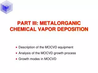
MOVPE = OMVPE = MOCVD • VPE using metalorganic species • It is most commonly used for deposition of III-V compounds From Ohring, Fig. 4-18, p. 187
MOCVD From Herman, Fig. 8.14 & 8.15, p. 180
Metalorganics From Herman, Fig. 8.21, p. 187
MOCVD From Hitchman, Appendix 6.3, p. 383
MOCVD From Ohring, Table 4-5, p. 187
MOCVD From Hitchman, Appendix 6.2, p. 382
MOCVD AsH3(g) + Ga(CH3)3(g) → GaAs(s) + 3CH4(g) TMG From Herman, p. 192
MOCVD From Herman, Fig. 8.23, p. 190
MOCVD From Herman, Fig. 8.17, p. 182
MOCVD From Ohring, Table 4-6, p. 189
CVD Films and Coatings From Ohring, Table 4-1, p. 154
CVD Kinetics • Viscous flow produces boundary layer at surfaces due to friction From Ohring, Fig. 4-7, p. 163
CVD Kinetics From Ohring, Fig. 4-8(a), p. 168 J(x,y) = C(x,y)v - DC(x,y) Boundary conditions: 1. Chemical reaction is complete at the surface C = 0 when y = 0 2. No net diffusion at the top of the reactor (gas molecules are reflected) dC/dy = 0 when y = b 3. Input source gas concentration is Ci C = Ci at x = 0
CVD Kinetics From Ohring, Fig. 4-8(a), p. 168 C(x,y) = (4Ci/p)sin(py/2b) exp (-p2Dx/4vb2) flux of gas toward surface (cm-2s-1) = J(x) = -D C(x,y)/y at y = 0 J(x) decreases along the direction x growth rate, R = J(x) / film atom density
CVD Kinetics • Growth rate declines along x-direction • Correct by increasing growth temperature along x-direction or tilting the substrates towards the gas flow From Ohring, Fig. 4-8(b), p. 168
AP-CVD From Jaeger, Fig. 6.9, p. 121
CVD Kinetics • Flux of gas molecules at the substrate surface: • Js = ksNs • ks = surface reaction rate constant (first order kinetics) • Ns = concentration of reactants above the surface • Flux of gas molecules diffusing from gas stream: • Jg = hg (Ng – Ns) • hg = mass transfer coefficient • Ng = gas concentration in the vapor
CVD Kinetics • At steady-state, • Js = Jg • Growth rate, • R = Js/N = [ kshg / (ks + hg) ] (Ng/N) • N = film atomic density
CVD Kinetics • ks = surface reaction rate constant • hg = mass transfer coefficient • ks >> hg • mass-transfer-limited growth • r = hgNg/N • r is temperature-insensitive • hg >> ks • surface-reaction-limited growth • r = ksNs/N is temperature sensitive
CVD Kinetics • Desired growth regime is in T-insensitive part of curve Mass-transfer-limited Surface-reaction-limited From Jaeger, Fig. 6.10, p. 122
PE-CVD • In conventional CVD chemical reactions are controlled by thermal energy provided by heating the substrate • The thermal energy provides the energy necessary to break bonds • In PE-CVD, a plasma is used to decompose the gas molecules for film deposition From Dobkin, Table 6-3, p 172
PE-CVD PECVD (N plasma) : 2SiH4 + N2(g) → 2SiNH(s) + 3H2(g) PECVD (Ar plasma) : SiH4(g) + NH3(g) → SiNH(s) + 3H2(g)
PE-CVD PE-CVD Capacitively Coupled Inductively Coupled Electron Cyclotron Resonance (ECR)
PE-CVD from Hitchman, Fig. 7.2, p. 392
ECR Plasma • Electrons in a B-field move in a circular path with the Larmor frequency: • w = eB/m • An em field at the Larmor frequency will be in phase with the electron motion and add energy to the electron on each orbit From Dobkin, Fig. 6-11, p 161
ECR Plasma • This effect is known as electron cyclotron resonance (ECR) • Normally w = 2.45 GHz and B = 875 Gauss From Ohring, Fig. 4-16, p. 184
ECR Plasma • Electrons are trapped by the field lines • Increased ionization (10-2 – 10-1) • Lower pressures (~10-4 – 10-2 Torr) • Greater plasma densities (~1012 cm-3) • Lower substrate temperatures (< 300 °C)