Download
1 / 28
280 likes | 444 Views
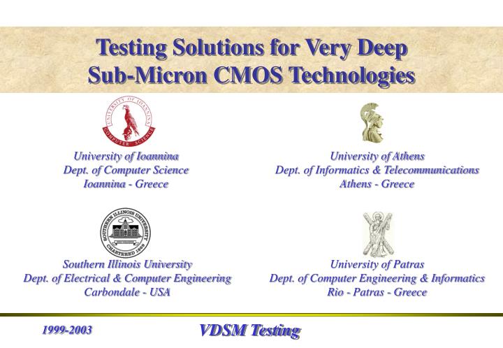
Testing Solutions for Very Deep Sub-Micron CMOS Technologies. University of Ioannina Dept. of Computer Science Ioannina - Greece. University of Athens Dept. of Informatics & Telecommunications Athens - Greece. Southern Illinois University Dept. of Electrical & Computer Engineering

E N D
Testing Solutions for Very Deep Sub-Micron CMOS Technologies University of Ioannina Dept. of Computer Science Ioannina - Greece University of Athens Dept. of Informatics & Telecommunications Athens - Greece Southern Illinois University Dept. of Electrical & Computer Engineering Carbondale - USA University of Patras Dept. of Computer Engineering & Informatics Rio - Patras - Greece
Delay Testing“On-Line and Off-Line DFT Techniques” • A Zero Aliasing Built-In Self Test Technique for Delay Fault Testing– DFT 1999 • A Versatile Built-In Self Test Scheme for Delay Fault Testing – DATE 2000
DFT for Delay Fault Testing Transition Detection Circuitry DFT-99 E
Off-Line Delay Testing DFT-99
On-Line Delay Testing DFT-99
Primary Inputs G-CLK TPG CUT n n N/T MUX Primary Outputs n m CUT TDU ENB m BICS m . . . ENB TDU ERR Dummy Buffers Virtual Ground ERR Primary Outputs DATE - 00 A Current Mode Technique for Delay Testing
Off-Line Delay Testing Test Phase Τ1 Τ2 Τ3 Τ4 Erroneous Response Valid Response Erroneous Response G-CLK dmax ENB End of Valid Data Output Responses Enable TDU Start of Current Test Phase Application of Vj Enable TDU End of Current Test Phase Start of Next Test Phase Application of Vj+1 Start of Valid Data Output Responses Disable TDU DATE - 00
On-Line Delay Testing Detection Phase j Detection Phase j-1 Detection Phase j+1 Τ1 Τ2 Τ3 Τ4 Erroneous Response Erroneous Response Valid Response CLK ENB Start of Detection Phase Input Ij Enable TDU End of Valid Data Output Responses Start of Detection Phase Input Ij+1 Enable TDU Start of Valid Data Output Responses Disable TDU Start of Valid Data Output Responses Disable TDU DATE - 00
Concurrent Testing“Soft and Timing Error Detection Circuits and Techniques” • A Hierarchical Architecture for Concurrent Soft Error Detection Based on Current Sensing– IOLTW 2002 • A Sense Amplifier Based Circuit for Concurrent Detection of Soft and Timing Errors in CMOS ICs – IOLTS 2003
Transient Pulse OUT FFO VDD OUT CLK ENB Preset ENB ERR FFO SN Error FF BICS ERR DTCT ENB Preset Action Sensing Mode Activation Circuit (AC) Current Mode Comparator Current Mode Comparator DTCT IOLTW - 02
Functional Circuit Cluster of Pairs OUT & FFO Pair OUT11 FFO1m FFOn1 OUT1m OUTn1 OUTnm FFO11 FFOnm 1st Level Activation AC11 AC1m ACn1 ACnm m m . . . . . . n N1 Nn . . . 2nd Level Pre-Sense CM1 CMn CL1 CLn IOLTW - 02 SN 3rd Level Final Sense Multiple Lines Current Sensing Comparator (ML-CSC) ERR CSC_out BICS EIF The Hierarchical Error Detection Architecture
Multiple Lines Current Sensing Comparator Multiple Lines Current Sensing Comparator ML-CSC OUT FFO VDD From the rest ACs of the cluster ENB Preset From the rest CMs ERR EIF N SN BICS CSC_out Activation Circuit (AC) ENB Current Mirror (CM) IOLTW - 02
Sense Amplifier Based Detector IOLTS - 03
Timing Waveforms IOLTS - 03
Detection Time vs Monitored Pairs IOLTS - 03
IDDQ Testing“The Challenge of VDSM Technologies” • Extending the Viability of IDDQ Testing in the Deep Submicron Era – ISQED 2002 • An Embedded IDDQ Testing Architecture and Technique– ISQED 2003
ITH Background Current Compensation Vdd CUT Vdd IDEF IB Leakage Fault Indication Output Compensator BICS T_EN EN BCC Gnd Gnd Higher Current Resolution ITH as low as BICS and/or BCC permit ISQED - 02
Vdd Vdd Vdd Vdd sub-CUTL sub-CUTR Fault Indication Output L Fault Indication Output R BICSL BICSR ENL ENR T_EN T_EN Gnd Gnd Gnd Gnd The BCC Based IDDQ Testing Technique IBL =RIBR IBR Current Mirror Amplifier R to L MIR_R_to_L BCC MIR_L_to_R Current Mirror Amplifier L to R IBL IBR =LIBL ISQED - 02
Power Supply Distribution CUT V_GndR V_GndL BCC & BICSs T_EN T_EN sub-CUTL sub-CUTR Gnd ISQED - 02
Scan Register • IEEE 1149.1 • IEEE P1500 • VSIA TST 2 1.0 0 1 0 1 SEL1 SEL2 SELn IDEF Multiple Current Sink BCC Implementation Background Current from sub-CUTR Background Current from sub-CUTL MIR_L_to_R IBR L2 IBL IBL SEL1 SEL2 SELn To the BICSR T_EN Current Mirror Amplifier W1/L W2/L Wn/L ISQED - 02 Gnd
Embedded IDDQ Testing ISQED - 03
IEEE 1149.1 Based IDDQ Testing Architecture ISQED - 03
IDDQ Testing Flow Diagram ISQED - 03
Power Supply Distribution ISQED - 03
Memory Testing“The Neighborhood Pattern Sensitive Fault Model” • A Test Pattern Generation Unit for Memory NPSF Built-In Self Test – ICECS 2000
A Deterministic TPG Unit ICECS - 00
FPGA Implementation ICECS - 00