Download
1 / 17
210 likes | 502 Views
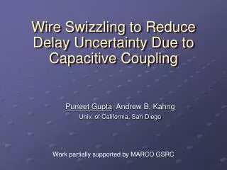
Coupling Between Wire Lines and Application to Transfer Impedance Analysis. Richard J. Mohr President, R. J. Mohr Associates, Inc. r.j.mohr@ieee.org. Rev. 7/19/04. IEEE/EMC 2004 – Coupling Between Wire Lines and Application to Transfer Impedance Analysis - All rights reserved .

E N D
Coupling Between Wire Linesand Application to Transfer Impedance Analysis Richard J. MohrPresident, R. J. Mohr Associates, Inc. r.j.mohr@ieee.org Rev. 7/19/04 IEEE/EMC 2004 – Coupling Between Wire Lines and Application to Transfer Impedance Analysis - All rights reserved
Cross Coupling in Interface Wiring • Cross coupling can occur via common return impedance, mutual inductance, and mutual capacitance ei =LWWIC Victim Wire CWWVC CWW LWW Source Wire IC VC VG
Employment of Ground Reference Plane • Ground plane reference provides low-impedance return; essentially eliminates coupling via common return. • Physical separation of signal lines minimizes mutual inductance and mutual capacitance. CWW LWW
Characteristics of Coupled Interference • Electrically coupled current (via mutual capacitance) • Current divides between source and load ends of victim • Net voltages at each end are equal and in-phase • Magnetically coupled voltage (via mutual inductance) • Voltage is series-injected and divides between source and load ends of victim • Voltages at each end are proportional to the impedance and tend to be out of phase • Electrically-induced voltages and magnetically induced voltages tend to reinforce at the source end and to cancel at the load end.
Mutual Inductance, Wires Over a Ground Plane Mutual Inductance, LWW (H/m)
Single-Point Grounding (SPG) of Return • Single-point grounding (SPG) of either (as illustrated) or both signal circuits eliminates coupling via common impedance and reduces mutual inductance LWW CWW
Employment of Twisted Pair Wiring • Twisting signal wire with its return essentially cancels mutual inductive coupling; capacitive coupling is slightly decreased
Effect of Wire Shield • Wire shield protects victim circuit by draining capacitively-coupled currents to ground through its low impedance. CWS
How Does Grounded Shield Protect Against Magnetic Induction? VO Vi LW Signal conductor + VO LWS Vi + LS RS IG Shield Shielded wire with grounded shield External magnetic field induces equal Vi in both wire and shield Equivalent circuit VO = IG(-jLWS + RS + jLS) + Vi - Vi But LWS = LS, and IG = Vi/(RS + jLS), therefore, VO/Vi = RS/(RS + jLS) At high frequencies, where LS>>RS, VO/Vi = RS/LS<<1 Shorted current in shield induces canceling voltage in shielded wire.
VO LW Signal conductor VO IW LWS LS RS IG Shield With shielded wire as a source, why does signal currentnot return entirely via low-impedance reference ground? Shielded wire with grounded shield Equivalent circuit Shield-Ground Plane mesh: 0 = IG(RS + jLS) -IW(jLS + RS - jLWS) But LWS = LS, therefore, IG/IW = RS/(RS + jLS), At High frequencies, where LS>>RS, IG/IW = RS/LS<<1 Shield return impedance is much lower than that of Reference ground plane loop
Attenuation Characteristics of Shielded Line • Net voltage relative to total induced voltage: VO/Vi = RS/(RS + jLS) • Net leakage current relative to internal shield signal current: IG/IW = RS/(RS + jLS) • The shielding effectiveness of the cable can be defined as: SE (dB) = 20 log (|RS + jLS | /RS) 20 log LS/RS • Note that in shielding calculations in general, and particularly at high frequencies, the shield resistance, RS, is replaced with the transfer impedance, of the shield, |ZT|
Inductance of a Wire Over a Ground Plane Inductance, LW (H/m)
Single-Shielded Cable (Note 1) Double-Shielded Cable (Note 2) Frequency (Hz) | ZT | (Ohms/m) SE (dB) | ZT | (Ohms/m) SE (dB) DC 0.015 - 0.008 - 0.1M 0.015 31.0 0.006 39.5 1 M 0.020 48.5 0.002 68.5 10 M 0.085 56.0 0.001 94.6 100 M 0.5 60.6 0.004 102.5 1000 M 5 60.6 0.04 102.5 Transfer Impedance and Shielding Effectiveness (SE) of Typical Cables • Notes: • Shield diameter: 0.116 inches; cable 2 inches over ground plane • SE (dB) = 20 log(2pfLS/|ZT|)
Summary of Shield Action In victim circuit, inductive voltage drop in shield return is precisely cancelled by the magnetically induced voltage in the signal circuit Net voltage induced in victim circuit is equal to the product of the shield current and the shield resistance acting as a transfer impedance The transfer impedance of a shield at frequencies below about 100 kHz (typically) is precisely equal to the resistance of the shield Depending on shield type and construction, at higher frequencies the transfer impedance can be lower or higher than the shield resistance
Selected References • Richard J. Mohr, “Coupling between Open and Shielded Wire Lines over a Ground Plane”, IEEE Transactions on Electromagnetic Compatibility, Vol. EMC-9, September 1967, pp. 34-45. • Richard J. Mohr, “Coupling between Lines at High Frequencies”, IEEE Transactions on Electromagnetic Compatibility, Vol. EMC-9, No. 3, December 1967, pp.127-129. • S.A. Schelkunoff & T.M. Odarenko, “Crosstalk between Coaxial Transmission Lines” Bell Systems Technical Journal, Vol. 26, April 1937, pp. 144-164. This paper is a classic- should be consulted when considering crosstalk in lines comparable to, or exceeding a wavelength in length.
End of Presentation Please close window to go back to CD or click to go to the Next Presentation.