Download
1 / 51
520 likes | 650 Views
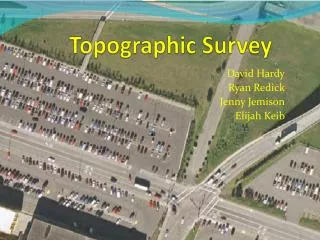
Topographic Survey S pecification for Urban Projects. Presented by Shane MacLaughlin, Atlas Computers Ltd Dr Paddy Prendergast, DIT. Overview.

E N D
Topographic Survey Specification for Urban Projects Presented by Shane MacLaughlin, Atlas Computers Ltd Dr Paddy Prendergast, DIT
Overview ‘A new specification designed to address the demanding needs of engineering design in a tightly constrained urban environment, in terms of consistency, accuracy, re-usability, and quality’
Background • QBN Experience pre-2005 • Inconsistent quality of surveys • Large amount of rework by engineers • Delivered work not fit for purpose • Need for improvement
Background • Surveyors experience • Weak specification • Poor statement of requirements • Falling prices leading to falling quality • Negative client feedback
Background • QBN topographic specification • Developed by Atlas Computers Ltd in conjunction with Dublin City Council QBN project office • Rigorously enforced consistency based on use of SCC software • Based on IG75 grid • Presented at Survey Ireland 2007 conference • Met stated objectives but had shortcomings
Shortcomings in 2007 spec • Lack of explicit QA/QC procedures • Lack of illustrative documentation for the contractor • Based on old IG75 grid rather than new grid • Based on implicit requirements through provision of SCC feature library
New specification • Overcome the shortcomings of the previous specification • Generalise the scope to include similar works • Form a working group representing the interests of all parties and including the necessary expertise to represent those interests
Working Group • Peter Muller, QBN Project Office • Tom Curran, Dublin City Council, Survey and Mapping Department • Shane MacLaughlin (Chair) and Áine Martin, Atlas Computers Ltd • Dr Paddy Prendergast, Irish Institute of Surveyors • Tom Mulreid, Apex Surveys and Society of Chartered Surveyors • Vincent Molloy, Local Government Computer Services Board • Ray Murphy and Stan Schoene, Murphy Surveys Ltd • Gerry Healy, RPS Consulting Engineers
Objectives • Include documented QA/QC procedures to verify the quality of the delivered product • Provide consistent results in terms of content, accuracy, and output • Move from IG75 to ITM while continuing to support IG75 • Achievable by the survey contractors • Cost effective for the client
Components • Introduction and executive summary • Specification main body • Feature library • User guide • Sample reports
Quality Assurance • What is quality? • ISO 9000 – Say what you do, do what you say, and be able prove it • ‘conformance to requirements’ – Phillip Crosby • To create quality we have to understand our requirements. ISO 8402-1986 standard defines quality as "the totality of features and characteristics of a product or service that bears its ability to satisfy stated or implied needs.“ • ‘Quality is value to some person or persons’ - Gerald Weinberg • Quality is subjective and exists within the context of providing value to a given audience. • ‘Staying in business’ - W Edwards Deming • Quality also relates to achieving the requirements with the available resources. In the context of providing services this amounts to meeting the needs of the client in a manner that is cost effective to both client and contractor. • ‘Quality is predictability’ - W Edwards Deming
QA and QC in the specification • Ensure all client requirements are clearly and unambiguously stated • Designed such that necessary checks and procedures are included to ensure that work being delivered meets stated requirements • Providing visible and meaningful quality checks within all aspects of the survey • Doing this in such a way that is achievable by the contractor and cost effective to the client • Recognizing the need for continuous improvement through revisions to the specification resulting from feedback from all stakeholders • Recognizing the limited scope of this particular specification, and the need to revisit the requirements to extend its scope
Consistency - Content • Feature library • Naming conventions • Colours, layers, styles • Annotation • Significance to the DTM • Output conventions to CAD, MX, etc… • Field implications • 1,2 and 3 point features • Strings and geometry
Consistency - Accuracy Missing Node Two reference points Manifestation Pseudo Node Duplicate Line Overshoot Undershoot Sliver No reference point Guptill & Morrison, 1995
Consistency - Accuracy Recorded Position 333333.333mE, 333333.333mN AA = 0.34m RMSE = ? True Position 333333.000mE, 333333.402mN • Absolute Accuracy - closeness of recorded position (coords) to its true position (Most Probable Value) – use GPS RA = 0.34m RMSE = ? Building Actual dimension on Ground = 4.12m Recorded dimension in Database = 3.78m Boundary Wall • Relative Accuracy - closeness between the recorded distance between two features in a database and the true distance Relative & Absolute Accuracy
Consistency - Accuracy • Horizontal & Vertical Accuracy - Control • Absolute - OSi GPS Network - 20mm for horizontal, but vertical = 2.5 times horizontal (satellite geometry) • Relative - a few mm possible with vertical (points fixed), but horizontal ~10mm (due to setting up errors) • Horizontal & Vertical Accuracy - Topographic detail • Absolute - width of pogo stick beside wall & trying to hold pogo vertical rather than centreline ~10cm • Relative - +/- 10cm at one end and +/-10cm at other end = +/-20cm • Hard & soft surfaces - block wall versus overgrown hedge with fence (horiz) or paved road versus ploughed field (vert)
Consistency - Accuracy EastingsNorthingsEllipsoidal Heights • Single shot NRTK observations are not suitable for survey control • Must be static observations, for a set period & post processed Accuracy (repeatability) - daily repeatability test by University of Melbourne (Gordini et al., 2006) - differences in metres between ‘true value’ and VRS solutions
Consistency - Output • Cartography • TIN ground model • Sections • Deliverables • CAD,SCC,MX • Raw data • Reports • Main survey report • Correction, reduction and adjustment details • Station location • Instrument set-up • Digital signing
0.7 m 0.5 m IG75 (Trig Network) 0.3m 0.1 m ITM IG75 (Polynomial) IG75 (7 parameter) Consistency – Grid System • Improvement in absolute accuracy from 0.65m to 0.05m if move from IG75 to ITM (using static GPS obs @ 20kms) • ITM recommended as primary CRS by Irish Institution of Surveyors in 2004 • Supply data in IG75 during intervening period for legacy systems & projects Active GPS Network = Passive GPS Network = Trig Network =
Consistency – Grid System • Benefits of using ITM • Surveys are GPS compatible • Computations simpler - no transformations • Significant improvement in absolute accuracy • Less impact of scale-factor • INSPIRE compatible • Using Grid in Quest • On www.osi.ie • Standalone on own PC • Embedded in software • New standard test to prove new versions from OSi & equipment suppliers
Establishing Control GPS Stations Traverse Stations • Horizontal Control – linear surveys • GPS baselines link traverses to ITM & provide extra rigor • Link to IG75 trig network not permitted (discontinued by OSi) • Constraints include: • Maximum distance between stations = 150m & maximum distance between GPS stations = 1500m • All stations must be inter-visible to at least 2 other stations • AA < ±25mm @ 95% confidence & RA < ±5mm
Establishing Control • Vertical Control – linear surveys • Hold 1 station fixed to GPS height in middle of network • Double levelling loop between stations using digital levels • AA < ±20mm & RA < ±10mm * k (where k =√ distance in kilometres) = ±3.9mm @ 150m • Link to Benchmarks not permitted (discontinued by OSi)
Establishing Control • Survey Control Report • Description of observation methodology (Horiz & Vert) • Description of adjustment methodology (Horiz & Vert) • QA checks (SOPs) applied in the field and during processing • Results - list of deliverables as well as map products • Certification by surveyor that information supplied is correct & company has Professional Indemnity Insurance • Copy of all raw data in standardised formats
Establishing Control • Survey Control Report • Schedule of results of control stations
Establishing Control • Survey Control Report • Traverse Route Diagram • GPS Network diagram
Establishing Control • Survey Control Report • Station error ellipses – quantify magnitude and orientation metrics of station accuracies
Establishing Control • Survey Control Report • Standardised location diagrams for control stations
Topography • RTK not allowed for surveying topographic features • Density of information • 10m on strings for sectioning • 10m spot level interval • Redundant measurements – to check & prove accuracy requirements are achieved • Report – to include info on standard operating procedures
Quality Control – Sources of error • Gross Errors (blunders - measurement & computation) • Misreading equipment, mis-recording a correct reading, casualness, verticality of pogo, GPS observations beside vegetation & buildings, rounding errors, …etc) • Eliminated by using standard operating procedures • Systematic errors (observation bias) • Pattern in observations - causes can be identified, size of error can be quantified - elimination by equipmentcalibration & P • Random errors (normal observation errors) • Due to range of different equipment specifications and observer’s competency - accuracy can be quantified statistically
Quality Control – Check Surveys • Method • Higher order of accuracy • Redundant measurements • No sight of main contract values • Use of independent contractors • Visual inspection for missing detail • Reporting
Check Surveys • Reports • Summaries for control and detail • Breakdown of errors and analysis • Problems highlighted
Auditing the digital data • QA check list • Analysing reports • Visual inspection • Topography • Sections • 3d surface
Auditing - QA Check list • Naming conventions adhered to • Model content is correct • No duplicate points • No crossing breaklines • No missing breaklines • Correct data included and excluded from the TIN • Accurate boundary • Correct annotation • etc….
Auditing – Accuracy and reports • Accuracy tolerances appear to have been achieved • Correct grid system has been used • Check corrections used are consistent • Check model is consistent with raw data • Check all specified items have been delivered • Check all files are digitally signed and check signatures
Dealing with non-compliant work • Need to enforce the specification • Good for the survey industry : Prices must be based around meeting the specification, accepting substandard work defeats competitive tendering • Good for the client : Quality and consistency improve quickly • Re-submission is at the contractors expense • The survey contractor should complete the QA process prior to submittal • Non compliant work should be rejected
Using the specification (Contractor) • Training • User guide • Rationale behind specific items • Using SCC to complete such items • Discussion of absolute and relative accuracy • Using SCC to process check surveys • Analysis of failed check surveys
Using the specification (Contractor) • Field tools • Onboard feature libraries • Leica • Trimble • PocketDTM • SCC
Using the specification (Client) • Training • Recommended usage • Check your requirements • Accuracy • Content • New features by group and category • Output formats • Grid • Cost expectation • QA implications for additions • Tools • SCC • Crystal reports
Results to date • Marked improvment in quality of delivered surveys • Errors discovered by QA process • Inconsistent application of scale • Accuracy shortfalls • Incorrect naming • GPS height processing • Failure to provide all necessary data • Missing services • Revisions to specification based on results • Support for GPS control • Changed accuracy statement • Standardising of reports • Additional reports
Distribution of first release • Intended audience • Local authorities • Surveying bodies • Engineers • Survey contractors • 500 printed copied, 1,000 electronic copies • Communications with RICS and TSA • Available electronically from Dublin City Council • http://www.dublincity.ie/RoadsandTraffic/QBNProjectOffice/Pages/TopographicSurveySpecification.aspx
Enhancements moving forward • Moving to open standards • LandXML • Broadly supported by a wide range of land survey and civil engineering packages • Used internationally • See http://www.landxml.org/ for further information • GML, to be included as part of the upcoming UK Highways Agency specification • See http://www.opengeospatial.org/standards/gml
Enhancements moving forward • Support for related survey activities • River surveys • Structures, building and bridge facades • Combined engineering / GIS surveys • Support for emerging and changing survey technologies • Scanners & LIDAR • Implications of using huge datasets • Feedback following release • Enhancements and revisions based on project feedback