Download
1 / 33
330 likes | 454 Views
Concept of KOYO-F and Formation of Aerosols and Micro Particles. T. Norimatsu Presented at TITAN workshop on MFE/IFE Common Research UCSD, Feb. 10-11, 2009. Common task on TITAN. To construct system integration model on tritium and thermo fluid system Identify key issues

E N D
Concept of KOYO-F and Formation of Aerosols and Micro Particles T. Norimatsu Presented at TITAN workshop on MFE/IFE Common Research UCSD, Feb. 10-11, 2009
Common task on TITAN • To construct system integration model on tritium and thermo fluid system • Identify key issues • & design priorities • Identify baseline design(s) • - FFHR, ARIES • - KOYO • Assess concept attractiveness • & feasibility • Perform analysis of key issues Goal Now….
Outline • Introduction of KOYO-F and the critical issues • Researches on chamber clearance • Code development (by H. Furukawa, ILT) • Experimental check 1 (by T. Norimatsu) • Experimental simulation with laser ablation(to be presented by K. A. Tanaka) • Experimental simulation on hydrodynamic instabilities on ablation by alpha particles(by Y. Shimada, ILT)
Conceptual laser fusion reactor KOYO-F based on fast ignition Electrical output power 1200 MW • Target gain 167 • Fusion yield 200MJ/shot • Laser 1.2 MJ x 16Hz,12% • 4 modular reactors with 32 compression beamsand 1 ignition beam • System efficiency 40%
Reactor with cascade flow of liquid LiPb • Coolant Li17Pb83 • Chamber/Blanket wall Ferrite / SiC/SiC • Fusion yield 200 MJ x 4 Hz • Thermal output 916 MW • Chamber size (inner/outer/high) 3m / 5m/14m • a pulse load 0.3 MJ/m2 • a peak load 2 x 10¹² W/m2 • Average thermal load 1.2 MW/m2 • Neutron load 5.6 MW/m2 • Solid angle of beam ports < 5% • TBR 1.3
Chamber KOYO-F with 32 beams for compression and one heating beam • Vertically off-set irradiation • Cascade surface flow with mixing channel • SiC panels coated with wetable metal • Tilted first panel to make no stagnation point of ablated vapor • Compact rotary shutters with 3 synchronized disks
Chamber The surface flow is mixed with inner cold flow step by step to reduce the surface temperature If the surface flow is a laminar flow, vapor pressure is too high to reach designated pressure of 5-10 Pa.
dt=0.5 oC/shotdt=1.3 oC/shot Chamber Thermal flow of KOYO-F Thermal shock in closed blanket Dp=0.1MPa
Dr Kunugi demonstrated a stable flow >3 mm using water Dr. Kajimura showed protection of the beam port by a 1T magnetic field. Critical issues in chamber 1(from J-US WS on reactor 2007) • Probability for direct exposure of the same place <1/103 – 1/104 • If we assume maintenance period of 2 years and acceptable erosion of 3-mm-thick, the probability for direct exposure of the same place with a particles must be less than 1/104. • Improve flow control, material selection, chamber radius • Protection of beam ports • Our first plan was to keep the surface temperature less than surrounding area to enhance the condensation. But this would not work because of the small temperature dependence of condensation. • Porous metal saturated with liquid LiPb • Magnetic field Liquid LiPb Dry surface
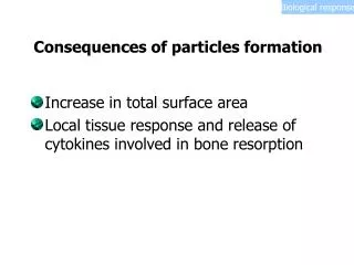
Critical issues in chamber 2(from J-US WS on reactor 2007) • Chamber clearance • Formation of aerosols • Large ( ~10 mm) particles due to RT instabilities and related secondary particles • Tritium diffusion through the heat cycle • To be solved during TITAN
Outline • Introduction of KOYO-F and the critical issues • Researches on chamber clearance • Code development (by H. Furukawa, ILT) • Experimental check 1 (by T. Norimatsu, ILE) • Experimental simulation with laser ablation(to be presented by K. A. Tanaka, Osaka U.) • Experimental simulation on hydrodynamic instabilities on ablation by alpha particles(by Y. Shimada, ILT)
We estimated the ablation process using ACORE. Stopping power in ionized vapor was calculated. Ziegler’s model Present model Ionization rate of Pb
ACONPL (Ablation and CONdensation of a PLume) p 11
Treatment of Phase Transition in ACONPL ○Equation of Motion of Ablation Surface ( The boundary of liquid and neutral gas or plasma ) Tv : Temperature of Ablation Surface Lv : Latent Heat of Vaporization ○Equation of Energy in Liquid Qp : Heat quantity due to charged particles Qx : Heat quantity due to absorption of X-ray If Ul >Ulcrt, Peeling will occur. Tvap : Vaporization Temperature p 12
Treatment of Hydro Dynamics in ACONPL ○ 1 Fluid and 2 Temperature Model, Lagrange Scheme 4-th term of right hand side is temperature increment due to phase transition from gas to liquid (clusterization). Pnv : numerical viscosity Vaporization Temperature ( Condensation Temperature ) q : Latent heat of Vaporization(Kelvin)
Condensation of a Plume ◯ Condensation Temperature q : Latent Heat of Vaporization(Kelvin) ◯Two-Phase Mixture Effects Condensation Rate Rate of Nucleation Cluster Growth Temperature of Clusters Reference B. S. Luk’yanchuk, S. I. Anisimov et. al., SPIE 3618 (1999) 434-452. Super Cooling Parameter p 16
To check the code, 10mm thick Pb membrane was heated and aerosols were captured on a witness plate.
There is geometrical effect on the diameter of particles. Geometrical effect The minimum diameter gives aerosol diameter. Model for large particles
Diameter of particles agreed with simulation result. Particles on continuous membrane The continuous membrane was formed with leading, super-cooled plume.
Density, Temperature and velocity profile of ablated material.
Density, Temperature and velocity profile of ablated material. T e 23 10 4 4 10 Time = 2000 ns 22 10 4 3 10 21 10 Number Density 20 10 v (m/s) 4 2 10 19 10 18 10 4 1 10 17 10 16 10 0 -1 0 1 2 3 4 5 x (cm)
15 10 2000 If interaction with opposite plume, clusters in this region will disappear after collisions with the opposite wall. 14 Time = 2000 ns 10 13 10 1500 12 10 11 10 1000 Clusters in this region expand to chamber volume before next target injection. The resulting nc at the next target injection is; 10 10 9 10 500 8 10 7 50 mm 10 0 -1 0 1 2 3 4 5 x (cm) Number density at the next target injection is estimated to be 107/cm3. T e n c 8 X 10⁶ /cm3
Influence of aerosols on target injection can be ignored. Chamber center Wall 3m Nc=107 cm3 Total mass of aerosols in the column 1.06 x 10⁻⁴ g (0.4 mm in the thickness of deposition layer) Aerosol mass = 2 x 10⁻⁴ Target mass We can ignore the influence on target trajectory.
Future work • Influence of ions as “seeds” for clusters • In this simulation, clusters move with fluid. • PIC code • Interaction with opposite plume • Stagnation at the center • Condensation on the opposite wall
Outline • Introduction of KOYO-F and the critical issues • Researches on chamber clearance • Code development (by H. Furukawa, ILT) • Experimental check 1 (by T. Norimatsu) • Experimental simulation with laser ablation(to be presented by K. A. Tanaka) • Experimental simulation on hydrodynamic instabilities on ablation by alpha particles(by Y. Shimada, ILT)
To understand the ablation phenomena by alpha particles, we used laser backlighting. • To know the influence of internal hot zone due to Bragg’s peak, we used back-light heating of Pb membrane. • Electric discharge was used to check simulation code for aerosol formation. Particle loads Energy deposition Volumetric heating Bragg’s peak
Experimental setup. Laser-scattering measurement was used to observe flying situation of metal Line focus 2×10⁻⁴ torr Probe laser 50 mm Scattered lights Laser CCD camera Target (glass plate with coated tin or lead) Punch out laser Glass plate Cylindrical lens 12 ms 15 ms 9 ms Nd:YAG laser Dot target Diameter:f500 mm (smaller than laser spot size) Intensity: 0.5 – 1 GW/cm2 Spot size : 700 - 800 mmφ Pulse duration : 15 ns 27
Spouted gas and small particles, and large particles were detected at 10-mm away from glass plate 6ms 9ms 12ms Gases Gases small particles 800mm 10 mm Averaged density 2×10¹⁸ (cm-3) 500mm 2ms 4ms 6ms 8ms 10ms 12ms Large particles 15ms Diameter ~10 μm 28
RT instability and break up would make larger( 3 mm), slow (100-500m/s) particles. Glass plate Gas, clusters High speed gases 3km/s High density columns Small particles RT Instability Dot target Large particles big particles 0.5km/s λ Depend on thickness of target etc. few joules energy It may cause secondary ablation of panel Laser 29
Tilted first panel concept may reduce the stagnation to 1/5 of cylinder case. 80% 20% (At end of after glow) Stagnation at the center needs more analysis Laser back lighting Electric discharge Planer heating Volumetric heating cosnj cos j Recently we started simulation on collisions of plumes. Preliminary result indicates condensation and formation of droplets are not critical because the kinetic energy of leading plume is much higher than latent heat of condensation.
Summary Aerosols and particles In KOYO-F, the diameter of aerosols 100 – 200 nm No influence on target trajectory and performanceif we ignore the interaction with opposite plume. Hydrodynamic process must be considered to discuss formation of particles. Remaining issue: Secondary particles More detailed estimation of stagnation at the chamber center 31
Lasers Cooled Yb:YAG ceramic laser will be used for both compression and ignition beams. compression Laser (1.1MJ, blue, ns) Main-Amplifier (~ MJ, NIR) 3rd Harmonics Pre-Amplifier (~ kJ, NIR) Fiber Oscillator Pulse Compressor 2nd Harmonics OPCPA Pulse Stretcher Heating Laser (0.1MJ, NIR, ps) Mode-lock Oscillator 60kJ x 8 beams Compression laser 1.1 MJ, 12% Heating laser 0.1 MJ, 5%
Target for KOYO-F Tritium burn ratio 23%