Download
1 / 10
100 likes | 281 Views
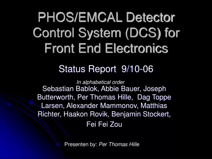
PHOS/EMCAL Detector Control System (DCS) for Front End Electronics. In alphabetical order. Sebastian Bablok, Abbie Bauer, Joseph Butterworth, Per Thomas Hille, Dag Toppe Larsen, Alexander Mammonov, Matthias Richter, Haakon Rovik, Benjamin Stockert, Fei Fei Zou. Status Report 9/10-06.

E N D
PHOS/EMCAL Detector Control System (DCS) for Front End Electronics In alphabetical order Sebastian Bablok, Abbie Bauer, Joseph Butterworth, Per Thomas Hille, Dag Toppe Larsen, Alexander Mammonov, Matthias Richter, Haakon Rovik, Benjamin Stockert, Fei Fei Zou Status Report 9/10-06 Presenten by: Per Thomas Hille
PHOS DCS for frontend electronics PVSS FED client (DIM) Intercom Layer FED server (DIM) Fee Client (DIM) PHOS FEEC Future system Current System APD GUI PC Configuration files 1 Command encoder Result decoder ”Command + data” BLOBs (SQL) Configuration Data base PC Readback result” 1 = Fee Client (DIM) 1 Service info Request service Service data Subscribe to service Ethernet DIM DNS ”Command + data” Detector Register service 20 Outside world Fee Server (DIM) PHOS CE ”Execute” DCS card 28 1 DCS/RCU Mezzanine ”Command + data” 1 1 RCU backplane RCU Readback”
The PHOS beamtest setup July-August 2006 (grossly simplified) Beam trigger PHOS Module Dual D-rorc Led trigger Trigger DCS + RCU DCS + RCU Pedestal trigger Switch Ethernet DCS + RCU DCS + RCU 4 DDL DCS network (master fee-net) DCS gateway Cern network (lxplus) DAQ Computer GUI
PABC GUIGraphical user interface to the PHOS/EMCAL DCS software
Preliminary result of the 2006 calibrationthe first PHOS module is in operation • Average working temperature of the PWO matrix: 16oC • Number of calibrated detector channels: 1825 • Gains of all the calibrated channels are equal within 4% () • Preliminary relative energy resolution for 2 GeV electrons (without fine tuning the gains) 5%. • At 16oC an average APD bias voltage 350 V, all the bias voltages are below 400 V will be even lower at 25oC • Some problems were found to be fixed in September The module at T10 beam-line Position of the calibrated channels (2/8 on top could not be reached with the beam, 1/8 had the HV problem) Channel gains at final APD bias voltages (2 GeV electron peak position) Relative energy resolution (very preliminary) Final APD bias voltage
DCS achievements before and during PHOS comissioning beamtest • APD bias controll. • Sucessfull calibration of 1825 channels. • Graphical user interface to DCS software/APD bias control made in ROOT. • Database for APD bias settings • Interaction with the database from the PABC GUI • PVSS • The full communication chain from the feeservers running on the DCS cards to PVSS (Thanks to Abbie Bauer and Joseph Butterworth). • Monitoring of simulated temperatures on the feeserver • New BC firmware that allows communication via the RCU slow control unit (Fei Fei Zou)
Status of PVSS/FSM integration • FEE Monitoring in PVSS • Communication chain from the DCS cards to PVSS is implementet (thanks to Abbie and Joey), but currently only with monitoring of simulated temperatures due to hardware problems of the FEE. • Status: Not finnished and not in Progress • FEE Configuration from PVSS • Low level software is implemented and was sucessfylly used during beamtest. Configuration with dedicated software, but not yet via PVSS. • Status: In progress
Remaining Tasks • Development of software for the feeserver to communicate with the PHOS version of the slow controll. • When : Depends on when PHOS module will be available for testing. • Responsible: Dag Toppe Larse + Per T (side activity) • Communication via PVSS with the PHOS/EMCAL DCS software. • When: January 2007 • Responsible: Per T (Only the communication chain) • PVSS + FSM implemantion of the whole DCS system. • When: ? • Responsible: Michail Bugolovski + Alexander Mammonov
Summary • Significant progress on the DCS implemetation during beamtest preparation and beamtest. Most of the bits and pieces are working, but it is not yet one integrated system. • We dont have any monitoring of the electronics • It is to few indians to have all the work done in time. • The electronics for PHOS is identical to EMCAL. We shoud take advantage of that and try to do as much as possible in a common effort. • We should try to reuse as much as possible of the TPC DCS system.