Download
1 / 11
110 likes | 216 Views
WBS7: Electronics and Data Acquisition. Overview (this talk): D. Casper Front-end Electronics: V. Paolone Data Acquisition: D. Casper FY06 Plans: P. Rubinov. Outline. WBS 7 Components Design Specifications Design Issues and Concerns Progress to Date and Near Term Plans

E N D
WBS7:Electronics and Data Acquisition Overview (this talk): D. Casper Front-end Electronics: V. Paolone Data Acquisition: D. Casper FY06 Plans: P. Rubinov
Outline • WBS 7 Components • Design Specifications • Design Issues and Concerns • Progress to Date and Near Term Plans • Cost and Schedule Overview • Cost and Schedule Issues and Concerns • Conclusions Electronics and DAQ
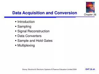
WBS 7: Electronics and DAQ • Front-end Electronics (7.1) • One FE board per MAPMT • High-voltage for MAPMTs • Digitization and Timing • CROCs and DAQ (7.2, 7.3) • One CROC per 48 MAPMTs • Three VME crates + computer • Front-end/computer interface • Distribute trigger and synchronization • Power and Rack Protection (7.4) • 48 V supplies, fanouts and interlock Electronics and DAQ
Specifications • MAPMT High-Voltage • PMT interface card or “base” (inside PMT box) • Controller on front-end board (outside PMT) • Charge and Time Measurement • Measure 1 – 200 photo-electrons • Measure relative hit time (on single front-end board) to a few nanoseconds • Synchronization • Measure global time (between front-end boards) to a few nanoseconds • Trigger • Tap into NuMI timing signals through MINOS • Readout • Handle rates up to 1 kHz (for PMT testing and calibration) • Control • MAPMT HV control and monitoring • Configuration • Power and Rack Protection (7 kW estimated requirement) Electronics and DAQ
Design Issues and Concerns • Need to test PMT “base” and HV subsystem • TriP or TriP-T? • TriP is known to work, but now obsolete • Need to test TriP-T • Triggering and Synchronization • Need to flesh-out interface with NuMI and MINOS • Understand what auxiliary electronics are required • Investigate possibility of self-triggering • Readout • Requirements for PMT testing unspecified • Requirements for Veto Wall unspecified • Infrastructure • Siting inside experimental hall needs to be understood • Concrete design of power distribution system does not exist Electronics and DAQ
Progress to Date/Near-Term Plans • Progress • Basic front-end board design concept tested successfully • LVDS chaining tested successfully (front-end boards only) • Near Term Plans • Continue tests of first front-end prototype • Test HV “base” design • Test and evaluate TriP-T • Begin design of second front-end prototype • Begin design of CROC prototype Electronics and DAQ
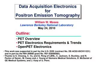
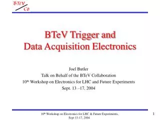
Cost and Schedule Overview (I) Electronics and DAQ
Cost and Schedule Overview (II) Electronics and DAQ
Cost and Schedule Overview (III) • Current schedule is out of date • e.g. CROC design did not begin on 6/1/05 and will not be completed on 9/20/05 • Projected Schedule • Front-End Boards: • PMT bases going out this week • Test PMT bases • TriP vs. TriP-T decision, then order • Begin 64-channel (second) prototype design (January ‘06) • Finish production and testing of 64-channel prototype (July ’06) • CROCs: • Should begin design as soon as possible • Finish production and testing of prototype by July ’06 • Note BOTH 64-channel front-end AND CROC prototypes are required for PMT testing (MSP file is missing an important constraint!) Electronics and DAQ
Cost and ScheduleIssues and Concerns • PMT Testing (WBS 6) Drives Our Schedule • Need to understand required components and coordinate schedules • M&S costs for prototypes (7.1.6 and 7.2.3) probably underestimated (depends on number required) • TriP Decision • Required before proceeding with design of second front-end prototype • Front-End Board Costs • Need to refine after switching to PMT base inside PMT box • Auxiliary Electronics • MINOS timing module for NuMI synchronization not explicitly included in WBS • Veto Wall DAQ Requirements (if any) Unspecified • Electronics Design • Paul is unavailable until roughly 1/06 • Design of CROC prototype should start as soon as possible Electronics and DAQ
Conclusions • Base Cost: $1,298,614 (total, no contingency) • M&S: $771,390 • Labor: $527,224 • Need to update after confirming the number of prototypes needed • Highest Contingency Items: • Front-End Production (Initial + Final): 20% $339,360 = $67,872 • Firm-up cost estimate in view of changes to HV subsystem • TriP Production & Checkout: 20%$70,000 + 100% $15,000 = $29,000 • Reason for large contingency not so clear • CROC Production: 50% $48,000 = $24,000 • Need a concrete design • Infrastructure (7.4) Contingency Currently Underestimated • $4,480 on $219,132 project ($124,600 M&S) seems too low • Schedule Risks: • Most important technical risks already addressed by front-end prototype • Only serious constraint is PMT testing • Understand the WBS 6 schedule • Begin work on CROC design in parallel to front-end Electronics and DAQ