Download

1 / 46
480 likes | 560 Views
Chapter 5 MASS, BERNOULLI AND ENERGY EQUATIONS. ZULFAKAR MOKHTAR TEL/WHATSAPP: 018-467 8160 (8AM-5PM weekdays).

E N D
Chapter 5MASS, BERNOULLI AND ENERGY EQUATIONS ZULFAKAR MOKHTAR TEL/WHATSAPP: 018-467 8160 (8AM-5PM weekdays)
Wind turbine “farms” are being constructed allover the world to extract kinetic energy fromthe wind and convert it to electrical energy.The mass, energy, momentum, and angularmomentum balances are utilized in the designof a wind turbine. The Bernoulli equation is alsouseful in the preliminary design stage.
Mass, Bernoulli and Energy Equations: • Mass, momentum, and energy equations, control volumes, Bernoulli approximation
5–1 ■INTRODUCTION You are already familiar with numerous conservation lawssuch as the lawsof conservation of mass, conservation of energy, and conservation ofmomentum. Historically, the conservation laws are first applied to a fixedquantity of matter called a closed systemor just a system, and then extendedto regions in space called control volumes. The conservation relations arealso called balance equationssince any conserved quantity must balanceduring a process. Many fluid flow devices such as thisPelton wheel hydraulic turbine areanalyzed by applying the conservationof mass and energy principles, alongwith the linear momentum equation.
the total rates of mass flow into and out of the controlvolume the rate of change of mass withinthe control volume boundaries. Conservation of Mass The conservation of mass relation for a closed system undergoing a changeis expressed as msys = constant or dmsys/dt = 0, which is the statement thatthe mass of the system remains constant during a process. Mass balance for a control volume(CV)in rate form: Continuityequation: In fluid mechanics, the conservation of massrelation written for a differential control volume is usually called the continuityequation.
The Linear Momentum Equation Linearmomentum:The product of the mass and the velocity of a body is called the linearmomentum or just the momentumof the body. The momentum of a rigidbody of mass mmoving with a velocity Vis mV. Newton’s second law:The acceleration of a body is proportional to the net force acting on itand is inversely proportional to its mass, and that the rate of change of themomentum of a body is equal to the net force acting on the body. Conservation of momentum principle:The momentum of a system remains constant only when the net force actingon it is zero, and thus the momentum of such systems is conserved. Linear momentum equation:In fluid mechanics, Newton’ssecond law is usually referred to as the linear momentum equation.
Conservation of Energy The conservation of energy principle (the energy balance):The net energy transfer toor from a system during a process be equal to the change in the energy contentof the system. Energy can be transferred to or from a closed system by heat or work. Control volumes also involve energy transfer via mass flow. the total rates of energy transfer into and out of thecontrol volume the rate of change of energy within the control volume boundaries In fluid mechanics, we usually limitour consideration to mechanical forms of energy only.
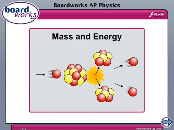
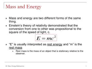
5–2 ■CONSERVATION OF MASS Conservation of mass: Mass, like energy, is a conserved property, and it cannot be created or destroyed during a process. Closed systems: The mass of the system remain constant during a process. Control volumes: Mass can cross the boundaries, and so we must keep track of the amount of mass entering and leaving the control volume. Mass is conserved even during chemical reactions. Mass m and energy E can be converted to each other: c is the speed of light in a vacuum, c = 2.9979108 m/s The mass change due to energy change is negligible.
Fun facts • If you could turn every one of the atoms in a paper clip into pure energy—leaving no mass whatsoever—the paper clip would yield 18 kilotons of TNT. • That's roughly the size of the bomb that destroyed Hiroshima in 1945. • On Earth, however, there is no practical way to convert a paper clip or any other object entirely to energy. • It would require temperatures and pressures greater than those at the core of our sun
Mass and Volume Flow Rates Mass flow rate:The amount of mass flowing through a cross section per unit time. The differential mass flow rate Point functions have exact differentials Path functions have inexact differentials The normal velocity Vnfor a surfaceis the component of velocityperpendicular to the surface.
Average velocity Volume flow rate Mass flow rate The volume flow rate is the volume of fluid flowing through a cross section per unit time. The average velocity Vavg is defined as the average speed through a cross section.
Conservation of Mass Principle The conservation of mass principle for a control volume: The net mass transfer to or from a control volume during a time interval t is equal to the net change (increase or decrease) in the total mass within the control volume during t. the total rates of mass flow into and out of the controlvolume the rate of change of mass withinthe control volume boundaries. Mass balance is applicable to any control volumeundergoing anykind of process. Conservation of mass principle for an ordinary bathtub.
The differential control volume dVand the differential control surfacedA used in the derivation of theconservation of mass relation.
The time rate of change of mass within the control volume plusthe net mass flow rate through the control surface is equal to zero. The conservation of mass equationis obtained by replacing B in theReynolds transport theorem bymass m, and b by 1 (m per unitmass =m/m = 1). A control surface should always beselected where it cronormal to the flow at alllocations sses the fluidflow to avoid complications, eventhough the result is the same.
Mass Balance for Steady-Flow Processes During a steady-flow process, the total amount of mass contained within a control volume does not change with time (mCV = constant). Then the conservation of mass principle requires thatthe total amount of mass entering a control volume equal the total amount of mass leaving it. For steady-flow processes, we are interested in the amount of mass flowing per unit time, that is, the mass flow rate. Multiple inlets and exits Single stream Many engineering devices such as nozzles, diffusers, turbines, compressors, and pumps involve a single stream (only one inlet and one outlet). Conservation of mass principle for a two-inlet–one-outlet steady-flow system.
Special Case: Incompressible Flow The conservation of mass relations can be simplified even further when the fluid is incompressible, which is usually the case for liquids. Steady, incompressible Steady, incompressible flow (single stream) There is no such thing as a “conservation of volume” principle. However, for steady flow of liquids, the volume flow rates, as well as the mass flow rates, remain constant since liquids are essentially incompressible substances. During a steady-flow process, volume flow rates are not necessarily conserved although mass flow rates are.
5–3 ■MECHANICAL ENERGY AND EFFICIENCY Mechanical energy:The form of energy that can be converted to mechanical work completely and directly by an ideal mechanical device such as an ideal turbine. Mechanical energy of a flowing fluid per unit mass: Flow energy + kinetic energy + potential energy Mechanical energy change: • The mechanical energy of a fluid does not change during flow ifits pressure, density, velocity, and elevation remain constant. • In the absenceof any irreversible losses, the mechanical energy change represents the mechanicalwork supplied to the fluid (if emech > 0) orextracted from thefluid (if emech < 0).
Mechanical energy is a useful conceptfor flows that do not involvesignificant heat transfer or energyconversion, such as the flow ofgasoline from anunderground tankinto a car.
Shaft work:The transfer of mechanical energy is usually accomplished by a rotatingshaft, and thus mechanical work is often referred to as shaft work. A pumpor a fan receives shaft work (usually from an electric motor) and transfers itto the fluid as mechanical energy (less frictional losses). A turbine converts the mechanical energy of a fluid to shaft work. Mechanicalefficiencyof a device or process The effectiveness of the conversion process between the mechanical work supplied or extracted and the mechanical energy of the fluid is expressed by the pump efficiencyand turbine efficiency,
The mechanical efficiency of a fan is the ratio of the kinetic energy of air at the fan exit to the mechanical power input.
Motor efficiency Generator efficiency Pump-Motor overall efficiency Turbine-Generator overall efficiency: The overall efficiency of a turbine–generator is the product of the efficiency of the turbine and the efficiency of the generator, and represents the fraction of the mechanical energy of the fluid converted to electric energy.
5–4 ■THE BERNOULLI EQUATION Bernoulli equation:An approximate relation between pressure,velocity, and elevation, and is valid in regions of steady, incompressibleflow where net frictional forces are negligible. Despite itssimplicity, it has proven to be a very powerful tool in fluid mechanics. The Bernoulliapproximation is typically useful in flow regions outside of boundary layersand wakes, where the fluid motion isgoverned by the combined effects ofpressure and gravity forces. The Bernoulli equation is anapproximate equation that is validonly in inviscid regions of flow wherenet viscous forces are negligibly smallcompared to inertial, gravitational, orpressure forces. Such regions occuroutside of boundary layers and wakes.
Acceleration of a Fluid Particle In two-dimensional flow,the acceleration can be decomposed into two components: streamwiseacceleration asalong the streamline and normal acceleration anin thedirection normal to the streamline, which is given asan =V2/R. Streamwise acceleration is due to a change in speed along a streamline, andnormal acceleration is due to a change in direction. For particles that movealong a straight path, an= 0 since the radius of curvature is infinity andthus there is no change in direction. The Bernoulli equation results from aforce balance along a streamline. During steady flow, a fluid may notaccelerate in time at a fixed point, butit may accelerate in space. Acceleration in steady flow is due to the change ofvelocity with position.
Derivation of the Bernoulli Equation Steady flow: Bernoulli equation Steady, incompressible flow: The forces acting on a fluid particlealong a streamline. The sum of the kinetic, potential, and flowenergies of a fluid particleis constant along a streamline during steady flow whencompressibilityand frictional effects are negligible. The Bernoulli equation between any two points on thesame streamline:
The incompressible Bernoulliequation is derived assumingincompressible flow, and thus itshould not be usedfor flows with significantcompressibility effects.
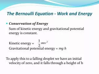
The Bernoulli equation can beviewed as the“conservation of mechanical energy principle.” • This is equivalentto the general conservation ofenergy principle for systems that do notinvolve any conversion of mechanical energy and thermal energy to eachother, and thus the mechanical energy and thermal energy are conserved separately. • The Bernoulli equation states that during steady, incompressible flowwith negligible friction, the various forms of mechanical energy are convertedto each other, but their sum remains constant. • There isno dissipation ofmechanical energy during such flows since there is no frictionthat converts mechanical energy to sensible thermal (internal) energy. • TheBernoulli equation is commonly used in practice since a variety of practicalfluid flow problems can be analyzed to reasonable accuracy with it. The Bernoulli equation states that thesum of the kinetic, potential, and flowenergies of a fluid particle is constantalong a streamline during steady flow.
Unsteady, Compressible Flow The Bernoulli equation for unsteady, compressible flow:
Static, Dynamic, and Stagnation Pressures Thekinetic and potential energies of the fluid can be converted to flow energy(and vice versa) during flow, causing the pressure to change.Multiplying the Bernoulli equation by thedensity gives P is the static pressure:It does not incorporate any dynamic effects; itrepresents the actual thermodynamic pressure of the fluid. This is thesame as the pressure used in thermodynamics and property tables. V2/2 is the dynamic pressure:It represents the pressure rise when thefluid in motion is brought to a stop isentropically. gz is the hydrostatic pressure:It is not pressure in a real sensesince its value depends on the reference level selected; it accounts for theelevation effects, i.e., fluid weight on pressure. (Be careful of the sign—unlikehydrostatic pressure gh which increases with fluid depth h, thehydrostatic pressure term gz decreases with fluid depth.) Totalpressure:The sum of the static, dynamic, and hydrostatic pressures. Therefore, the Bernoulli equation states that the total pressurealong a streamline is constant.
Limitations on the Use of the Bernoulli Equation • Steady flowThe Bernoulli equation is applicable to steady flow. • Frictionless flowEvery flow involves some friction, no matter how small, and frictional effects may or may not be negligible. • No shaft workThe Bernoulli equation is not applicable in a flow section that involves a pump, turbine, fan, or any other machine or impeller since such devices destroy the streamlines and carry out energy interactions with the fluid particles. When these devices exist, the energy equation should be used instead. • Incompressible flowDensity is taken constant in the derivation of the Bernoulli equation. The flow is incompressible for liquids and also by gases at Mach numbers less than about 0.3. • No heat transferThe density of a gas is inversely proportional to temperature, and thus the Bernoulli equation should not be used for flow sections that involve significant temperature change such as heating or cooling sections. • Flow along a streamlineStrictly speaking, the Bernoulli equationis applicable along a streamline. However, when a region of the flow is irrotational and there is negligibly small vorticity in the flow field, the Bernoulli equation becomes applicable across streamlines as well.
Frictional effects, heat transfer, and components thatdisturb the streamlined structure offlow make theBernoulli equation invalid. It shouldnot be used in any of the flows shownhere. When the flow is irrotational, theBernoulli equation becomes applicablebetween any two points along the flow(not just on the same streamline).
Hydraulic Grade Line (HGL)and Energy Grade Line (EGL) It is often convenient to represent the level of mechanical energy graphicallyusing heightsto facilitate visualization of the various terms of the Bernoulliequation. Dividing each term of the Bernoulli equation by ggives P/g is the pressure head; it represents the height of a fluid column thatproduces the static pressure P. V2/2g is the velocity head; it represents the elevation needed for a fluidto reach the velocity V during frictionless free fall. z is the elevation head; it represents the potential energy of the fluid. An alternative form of the Bernoulliequation is expressed in terms ofheads as: The sum of the pressure,velocity, and elevation heads isconstant along a streamline.
Hydraulic grade line (HGL), P/g + zThe line that represents the sum of the static pressure and the elevationheads. Energygrade line (EGL), P/g + V2/2g + zThe line thatrepresentsthe total head of the fluid. Dynamic head,V2/2gThe difference between the heights of EGL and HGL. The hydraulic grade line (HGL) andthe energy grade line (EGL) for freedischarge from a reservoir through ahorizontal pipe with a diffuser.
Noteson HGL and EGL • For stationary bodiessuch as reservoirs or lakes, the EGL and HGLcoincide with the free surface of the liquid. • The EGL is always a distance V2/2g above the HGL. These two curvesapproach each other as the velocity decreases, and they diverge as thevelocity increases. • In an idealized Bernoulli-type flow, EGL is horizontal and its heightremains constant. • For open-channel flow, the HGL coincides with the free surface of theliquid, and the EGL is a distance V2/2g above the free surface. • At a pipe exit, the pressure head is zero (atmospheric pressure) and thusthe HGL coincides with the pipe outlet. • The mechanical energy lossdue to frictional effects (conversion tothermal energy) causes the EGL and HGL to slope downward in thedirection of flow. The slope is a measure of the head loss in the pipe. Acomponent, such as a valve, that generates significant frictional effectscauses a sudden drop in both EGL and HGL at that location. • A steep jump/dropoccurs in EGL and HGL whenever mechanical energy is added or removed to or from the fluid (pump, turbine). • The (gage) pressure of a fluid is zero at locations where the HGLintersects the fluid. The pressure in a flow section that lies above the HGLis negative, and the pressure in a section that lies below the HGL ispositive.
Example: Water Discharge from a Large Tank Example: Spraying Water into the Air
5–5 ■GENERAL ENERGY EQUATION The energy change of a systemduring a process is equal to the network and heat transfer between thesystem and its surroundings. The first law of thermodynamics (the conservation of energy principle): Energy cannot be created ordestroyed during a process;it can only change forms.
Energy Transfer by Heat, Q Thermal energy: The sensible and latent forms of internal energy. Heat Transfer:The transfer of energy from one system to another as a result of a temperature difference. The direction of heat transfer is always from the higher-temperature body to the lower-temperature one. Adiabatic process:A process during which there is no heat transfer. Heat transfer rate:The time rate of heat transfer. Temperature difference is the driving force for heat transfer. The larger the temperature difference, the higher is the rate of heat transfer.
Energy Transfer by Work, W • Work:The energy transfer associated with a force acting through a distance. • A rising piston, a rotating shaft,andan electric wire crossing the system boundaries are all associated with work interactions. • Power: The time rate ofdoing work. • Car engines and hydraulic,steam, and gas turbines produce work; compressors, pumps, fans, and mixersconsume work. WshaftThe work transmitted by a rotating shaft WpressureThe workdone by the pressure forces on the control surface WviscousThe work doneby the normal and shear components of viscous forces on the control surface WotherThe work done by other forces such as electric, magnetic,and surface tension
Shaft Work The power transmitted through the shaft is the shaft work done per unit time: Shaft work is proportional to the torque applied and the number of revolutions of the shaft. Energy transmission through rotating shafts is commonly encountered in practice.