Download
1 / 33
650 likes | 1.44k Views
PTT 201/4 THERMODYNAMIC SEM 1 ( 2013/2014). CHAPTER 5 : Mass and Energy Analysis of Control Volumes. CONSERVATION OF MASS. Conservation of mass : Mass, like energy, is a conserved property, and it cannot be created or destroyed during a process.

E N D
PTT 201/4THERMODYNAMIC SEM 1 (2013/2014) CHAPTER 5: Mass and Energy Analysis of Control Volumes
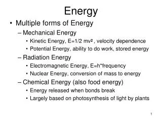
CONSERVATION OF MASS Conservation of mass: Mass, like energy, is a conserved property, and it cannot be created or destroyed during a process. Closed systems: The mass of the system remain constant during a process. Control volumes: Mass can cross the boundaries, and so we must consider the amount of mass entering and leaving the control volume. Mass m and energy E can be converted to each other according to where c is the speed of light in a vacuum, which is c = 2.9979108 m/s.
Mass flow rate Mass and Volume Flow Rates Volume flow rate
These equations are often referred to as themass balanceand are applicable to any control volume undergoing anykind of process. Conservation of Mass Principle The conservation of mass principle for a control volume: The net mass transfer to or from a control volume during a time interval t is equal to the net change (increase or decrease) in the total mass within the control volume during t.
Conservation of Mass Principle (cont) General conservation of mass in rate form
Mass Balance for Steady-Flow Processes During a steady-flow process, the total amount of mass contained within a control volume does not change with time (mCV = constant). For steady-flow processes, we are interested in the amount of mass flowing per unit time, that is, the mass flow rate. The conservation of mass principle requires thatthe total amount of mass entering a control volume equal the total amount of mass leaving it. Multiple inlets and exits Single stream Many engineering devices such as nozzles, diffusers, turbines, compressors, and pumps involve a single stream (only one inlet and one outlet).
Steady, incompressible flow (multiple stream) Steady, incompressible flow (single stream) Special Case: Incompressible Flow The conservation of mass relations can be simplified even further when the fluid is incompressible (constant density), which is usually the case for liquids. There is no such thing as a “conservation of volume” principle. For steady flow of liquids, the volume flow rates, as well as the mass flow rates, remain constant since liquids are essentially incompressible substances.
Example 5-1: Water flow through a garden hose nozzle A garden hose attached with a nozzle is used to fill a 40-L bucket. The inner diameter of the hose is 2 cm, and it reduces to 0.8 cm at the nozzle exit as shown in figure. If it takes 50 s to fill the bucket with water, determine: the volume and mass flow rates of water through the hose the average velocity of water at the nozzle exit.
Home Task • EXAMPLE 5-2 Please try the following examples:
FLOW WORK AND THE ENERGY OF A FLOWING FLUID Flow work, or flow energy: The work (or energy) required to push the mass into or out of the control volume. This work is necessary for maintaining a continuous flow through a control volume.
Total Energy of a Flowing Fluid The flow energy is automatically taken care of by enthalpy. In fact, this is the main reason for defining the property enthalpy. h = u + Pv The total energy consists of three parts for a nonflowing fluid and four parts for a flowing fluid.
Energy Transport by Mass When the kinetic and potential energies of a fluid stream are negligible When the properties of the mass at each inlet or exit change with time as well as over the cross section
Example 5-3: Energy Transport by Mass Steam is leaving a 4-L pressure cooker whose operating pressure is 150 kPa as shown in figure. It is observed that the amount of liquid in the cooker has decreased by 0.6 L in 40 min after the steady operating conditions are established, and the cross-sectional area of the exit opening is 8 mm2 . Determine : (a) The mass flow rate of the steam and the exit velocity (b) The total energy and flow energies of the steam per unit mass (c) The rate of which energy leaves the cooker by steam.
ENERGY ANALYSIS OF STEADY-FLOW SYSTEMS Steady-flow process:A process during which a fluid flows through a control volume steadily.
Mass and Energy balances for a steady-flow process A water heater in steady operation. Mass balance Energy balance
when kinetic and potential energy changes are negligible Energy balance relations with sign conventions (i.e., heat input and work output are positive)
SOME STEADY-FLOW ENGINEERING DEVICES Many engineering devices operate essentially under the same conditions for long periods of time. The components of a steam power plant (turbines, compressors, heat exchangers, and pumps), for example, operate nonstop for months before the system is shut down for maintenance. Therefore, these devices can be conveniently analyzed as steady-flow devices. A modern land-based gas turbine used for electric power production. This is a General Electric LM5000 turbine. It has a length of 6.2 m, it weighs 12.5 tons, and produces 55.2 MW at 3600 rpm with steam injection.
Nozzles and Diffusers Nozzles and diffusers are commonly utilized in jet engines, rockets, spacecraft, and even garden hoses. A nozzleis a device that increases the velocity of a fluidat the expense of pressure. A diffuseris a device that increases the pressure of a fluidby slowing it down. Energy balance for a nozzle or diffuser:
Example 5-4: Deceleration of Air in a Diffuser Air at 10˚C and 80 kPa enters the diffuser of a jet engine steadily with a velocity of 200 m/s. The inlet area of the diffuser is 0.4 m2. The air leaves the diffuser with a velocity that is very small compared with the inlet velocity. Determine : (a) The mass flow rate of the air (b) The temperature of the air leaving the diffuser.
Example 5-5: Acceleration of Steam in a Nozzle Steam at 180MPa and 400˚C steadily enters a nozzle whose inlet area is 0.02 m2. The mass flow rate of the steam through the nozzle is 5 kg/s. Steam leaves the nozzle at 1.4 MPa with a velocity of 275 m/s. Heat losses from the nozzle per unit mass of the steam are estimated to be 2.8 kJ/kg. Determine : (a) The inlet velocity (b) The exit temperature of the steam
Turbines and Compressors Turbine drives the electric generator in steam, gas, or hydroelectric power plants. As the fluid passes through the turbine, work is done against the blades, which are attached to the shaft. As a result, the shaft rotates, and the turbine produces work. Compressors, as well as pumps and fans, are devices used to increase the pressure of a fluid. Work is supplied to these devices from an external source through a rotating shaft. A fanincreases the pressure of a gas slightly and is mainly used to mobilize a gas. A compressoris capable of compressing the gas to very high pressures. Pumpswork very much like compressors except that they handle liquids instead of gases.
Example 5-6: Compressing Air by a Compressor Air at 100 kPa and 280 K is compressed steadily to 600 kPa and 400 K. The mass flow rate of the air is 0.02 kg/s, and the heat loss of 16 kJ/kg occurs during the process. Assuming the changes in kinetic and potential energies are negligible. Determine the necessary power input to the compressor. Energy balance for the compressor in this figure:
Example 5-7: Power Generation by a Steam Turbine The power output of an adiabatic steam turbine is 5 MW, and the inlet and exit conditions of the steam are indicated as shown in figure. (a) Compare the magnitudes of ∆h, ∆ke and ∆pe (b) Determine the work done per unit mass of the steam flowing through the turbine. (c) Calculate the mass flow rate of the steam
Throttling valves Throttling valves are any kind of flow-restricting devices that cause a significant pressure drop in the fluid. The pressure drop in the fluid is often accompanied by a large drop in temperature, and for that reason throttling devices are commonly used in refrigeration and air-conditioning applications.
Example 5-8: Expansion of Refrigerant-134a in a Refrigerator Refrigerant-134a enters the capillary tube of a refrigerator as saturated liquid at 0.8 MPa and is throttled to a pressure of 0.12 MPa. Determine: The quality of the refrigerant at the final state The temperature drop during this process Energy balance:
Mixing chambers In engineering applications, the section where the mixing process takes place is commonly referred to as a mixing chamber.
Example 5-9: Mixing of Hot and Cold Water in a Shower Consider an ordinary shower where hot water at 60˚C is mixed with cold water at 10˚C. If it is desired that a steady stream of warm water at 45˚C be supplied, determine the ratio of the mass flow rates of the hot to cold water. Assume that the heat losses from the mixing chamber to be negligible and the mixing to take place at a constant pressure of 150 kPa. Energy balance for the adiabatic mixing chamber in the figure is:
Heat exchangers Heat exchangers are devices where two moving fluid streams exchange heat without mixing. Heat exchangers are widely used in various industries, and they come in various designs. The heat transfer associated with a heat exchanger may be zero or nonzero depending on how the control volume is selected. A heat exchanger can be as simple as two concentric pipes.
Example 5-10: Cooling of Refrigerant-134a by Water Refrigerant-134a is to be cooled by water in a condenser. The refrigerant enters the condenser with a mass flow rate of 6 kg/min at 1 MPa and 70˚C and leaves at 35˚C. The cooling water enters at 300 kPa and 15˚C and leaves at 25˚C. Neglecting any pressure drops, determine: The mass flow rate of cooling water required The heat transfer rate from the refrigerant to water Mass and energy balances for the adiabatic heat exchanger in the figure is:
Pipe and duct flow The transport of liquids or gases in pipes and ducts is of great importance in many engineering applications. Flow through a pipe or a duct usually satisfies the steady-flow conditions. Heat losses from a hot fluid flowing through an uninsulated pipe or duct to the cooler environment may be very significant. Pipe or duct flow may involve more than one form of work at the same time.
Example 5-11: Electric Heating of Air in a House The electric heating systems used in many hoses consist of a simple duct with resistance heaters. Air is heated as it flows over resistance wires. Consider a 15-kW electric heating system. Air enters the heating section at 100 kPa and 17˚C with a volume flow rate of 150 m3/min. If heat is lost from the air in the duct to the surroundings at a rate of 200 W, determine the exit temperature of air. Energy balance for the pipe flow shown in the figure is
Summary • Conservation of mass • Mass and volume flow rates • Mass balance for a steady-flow process • Mass balance for incompressible flow • Flow work and the energy of a flowing fluid • Energy transport by mass • Energy analysis of steady-flow systems • Some steady-flow engineering devices • Nozzles and Diffusers • Turbines and Compressors • Throttling valves • Mixing chambers and Heat exchangers • Pipe and Duct flow