Download
1 / 36
700 likes | 1.8k Views
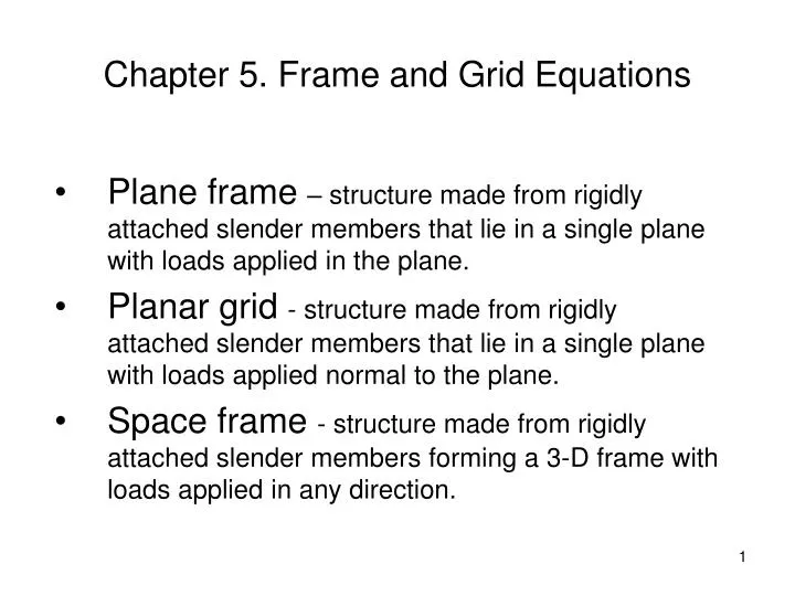
Chapter 5. Frame and Grid Equations. Plane frame – structure made from rigidly attached slender members that lie in a single plane with loads applied in the plane.

E N D
Chapter 5. Frame and Grid Equations • Plane frame – structure made from rigidly attached slender members that lie in a single plane with loads applied in the plane. • Planar grid - structure made from rigidly attached slender members that lie in a single plane with loads applied normal to the plane. • Space frame - structure made from rigidly attached slender members forming a 3-D frame with loads applied in any direction.
Plane frame Example: bicycle frame Note: multiforce members – combined axial and bending loads. Finite element formulation combines truss and beam element formulations
Planar Grid Members must transmit bending and torsion loads (no axial loading)
Space Frame Members must transmit axial, bending and torsion loads
0 0 0 0 0 0 0 0 0 0 10,000 5,000 Plane Frame Example Problem 1Global Equations K Solve six equations (eqs. 4-9)
Planar Grid Members must transmit bending and torsion loads (no axial loading)
Grid Equations • Planar grid - structure made from rigidly attached slender members that lie in a single plane with loads applied normal to the plane. • Members must transmit bending and torsion loads (no axial loading)
Grid Element: Local Coordinates Nodal degrees of freedom: Nodal loads / moments: Note: Grid element deforms by bending in the x-y plane and torsion about the x-axis
Grid Element: Local Coordinates(cont.) Sign conventions for torque:
Grid element – bending deformation From Chapter 4: Note moments and rotations are about the z-axis
Grid element - Torsion - angle of twist Assume linear interpolation:
Grid element – Torsion (cont.) Element equations (torsion): where G – shear modulus, L – element length and J – torsional constant
Grid Element: Global Coordinates Coordinate transformation in x-z plane only:
Grid Element: Example (cont.) Element 1 Element stiffness matrix (node 2 degrees of freedom only)
Grid Example (cont.) Element 2 Element stiffness matrix (node 2 degrees of freedom only)
Grid Example (cont.) Global Equations: Solution:
Grid Example (cont.) Element loads and moments: Element 1 Element 2
Space Frame(Beam element arbitrarily oriented in space) Deformation modes: Bending about y and z axes Axial load in x direction (not shown in figure) Torsion about x axis (not shown in figure)
Space Frame(cont.) Bending in the plane Bending in the plane
Space Frame(cont.) Axial load in x - direction Torsion about the x – axis
Space Frame(cont.) Element stiffness matrix (local coordinates):
Space Frame:Transformation to Global Coordinates Directions cosines:
Space Frame:Transformation to Global Coordinates (cont.) Element stiffness matrix (global coordinates) where
Space Frame Example (cont.) Global equations (node 1 terms only) Solution
Space Frame Example (cont.) Element loads & moments: