Download
1 / 33
330 likes | 351 Views
This report provides updates on the timing counter (TC) project, including activities such as tests on PM characteristics, Montecarlo activities, and possible new ideas. Preliminary results, tests in a magnetic field, and future plans are also discussed.

E N D
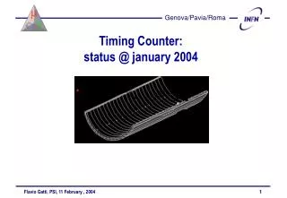
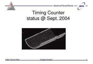
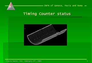
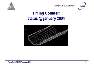
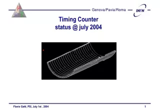
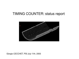
TIMING COUNTER: status report Giorgio CECCHET, PSI July 11th, 2003
Timing counter • MC activities • Tests on PM characteristics • Preliminary results of May test • Tests in magnetic field • Possible new ideas on “transverse counter”
Montecarlo activities • Reorganization of code repository • Critical revision of TC code • Rievaluation of main geometrical parameters of TC
Length 70 cm Angle (-140,10)° Radius 28.2 0.5 29.0 2.0
Tests on PM characteristics • Basic tests on gain and TTS • Photomultiplier used Hamamatsu fine mesh 1,5”, 19 dynodes H8409-70mod
Serial n. Q.E. % (500nm) VMCP (10^6) Noise (0.5 p.e.) 3256 19,2 2450V 100kHz 7237 18,5 2160V 140kHz MMICRO CHANNEL PLATE PMT Active diameter: 20 mm Test wavelength 670 nm Ligh spot diameter 8 mm
May 2003 test • On May 2003 two scintillators (80x5x1) assembled with 1.5” and 2” PM’s and taken to pE5 area • Aim: measure rough count rate in conditions similar to final
Main results Position similar to final in the Cobra (30 cm off beam axis) Rates: Beam off -> Bck: 25evs/s Beam on, no mu stopper -> 0.5 Mhz Beam on, with mu stopper -> 5 Mhz PMT saturation: 25Hz->10KHz : 1.8 V/pulse 20KHz: 1.7V/pulse 200KHz: 0.4 V/ pulse PMT with higher anode current are nedeed (2” PM better than 1.5”) Need to design a higher current voltage divider?
With collimated beam (10 mm dia.): measure of arrival time differences between 2 PMTs and calculation of time resolution FWHM using the formula: Sigma*2.35/sqrt(2) We obtain 175 ps FWHM for the single PMT, in absence of magnetic field.
Magnetic field tests • One week ago magfield tests started • Conventional magnet in LASA (Milan) with 12 cm headroom and field up to 1.2 Tesla water cooled
Setup used • A very simple setup was used to take the light from a blue diode to the photocathode
New ideas • Investigate the possibility of using a 5x5 mm2 APD from Hamamatsu to readout optical fibers as transverse (trigger) counter. • Few samples made available from PSI and under investigation in Genoa
More work to be done • Complete timing test on single PM in magnetic field • Test scintillator coupled to PM’s in magfield (MARISA) • Full testing of APD’s and optical fibers • Exploit the full capabilities of fine mesh PM’s (new voltage divider?....) • Engineering test of 3-4 scintillators and similar number of fibers during Oct-Nov beam time
B field measurements: planned form july 15 to 30 • Rotable support for 1-2 PMT/MCP for MARISA magnet under construction. • B= 0-1.6 T • Measurement of single PMT parameters (gain/TTS vs B) at different angles with B • 2-PMTs and scintillators assembly.
Schedule • We think now we do not have yet enough infos to make a correct choice of the PM to be used in the TC. We are confident that the new tests will lend us to a reliable decision.
2002 2003 2004 2005 PMT Evaluation PMT Design Design Manufactoring Assembly Test Milestone