Download
1 / 20
200 likes | 310 Views
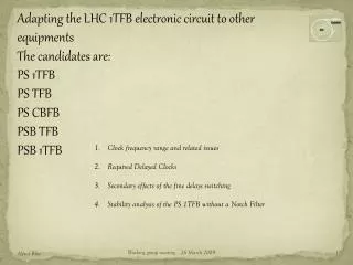
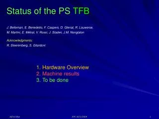
Status of the PS TFB Upgrade launched in July 2005. L. Arnaudon, A. Blas, F. Caspers, D. Glenat, R. Louwerse, V. Rossi. Background System block-diagram Hardware overview Planning. PS TFB. Background.

E N D
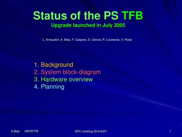
Status of the PS TFBUpgrade launched in July 2005 L. Arnaudon, A. Blas, F. Caspers, D. Glenat, R. Louwerse, V. Rossi • Background • System block-diagram • Hardware overview • Planning APC meeting 20/4/2007
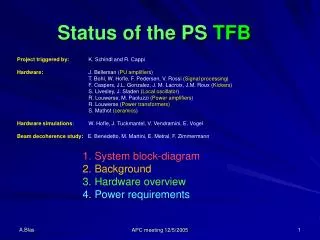
PS TFB Background 05/05 Presentation to the APC to ask for some founding (new amplifiers, Strip line kicker upgrade kicker impedance matching transformers, PLC control system, LHC type electronic core …) System specified for < +/- 2mm injection errors and compatibility with LHC: End 06System expected to be ready APC meeting 20/4/2007
PS TFB Block diagram Blue boxes represent new hardware since 6/05 APC meeting 20/4/2007
PS TFB Pick-up amplifiers (J. Belleman) Were ready in October 2003 BW: 20 kHz – 40 MHz 80 dB dynamic range (compatible with ions) Remotely programmable gain Located in the ring below concrete slab APC meeting 20/4/2007
PS TFB Electronic core Ongoing design using the hardware foreseen for the LHC 1TFB Ready in late 2007 ????. APC meeting 20/4/2007
PS TFB Electronic core APC meeting 20/4/2007
PS TFB Clock generation (J. Sladen) 1 GHz DDS Available since mid-2004 Receives the frequency program from the PS central building and outputs the 160*Frev (< 80 MHz). APC meeting 20/4/2007
PS TFB Pre-Amplifier • Fast Clipping of the output signal • 0 and 180o outputs • Programmable gain • TFM setup • Local / Remote control • Interface with the PLC control • Compatible with analogue systems APC meeting 20/4/2007
PS TFB Power Amplifier [2.5 kHz – 23 MHz], 3kW – 5ms, 750W - CW 4 amplifiers required + 2 spares 2 amplifiers ready used in 2006 MDs 3 amplifiers under final tests 1 amplifier under construction waiting for missing material APC meeting 20/4/2007
PS TFB Power Amplifier Power Response (inactive trace = version used in MD) Amplitude Phase APC meeting 20/4/2007
PS TFB Impedance matching transformers Input impedance: 50 Ω Output impedance: 100 Ω Each coax: 50 Ω Voltage gain = 2 [ 2kHz – 40 MHz] up to 3 kW APC meeting 20/4/2007
PS TFB Kicker APC meeting 20/4/2007
PS TFB Kicker APC meeting 20/4/2007
PS TFB Power loads 100Ω to 50Ω resistive transition [ DC – 190 MHz] 1.6 kW CW 50 Ω / 30 dB Attenuator [ DC – 1GHz] 1 kW CW APC meeting 20/4/2007
PS TFB Power Control APC meeting 20/4/2007
PS TFB Water cooling Electric valves coupled to leak detectors APC meeting 20/4/2007
PS TFB LHC 26 GeV + MTE MD setup APC meeting 20/4/2007
PS TFB 26 GeV MD setup 2100 ns Notch delay + 1340 ns 1-turn-delay APC meeting 20/4/2007
PS TFB MD’s MTE blow-up at 14 GeV, Oct.2006, A. Franchi, S. Gilardoni, M. Giovannozzi, D. Quatraro See APC slides 9 March 2007 26 GeV, LHC beam transverse damping, Oct. - Nov. 2006. R. Steerenberg, G. Arduini, E. Benedetto, H .Damereau, A. Grudiev, W. Höfle, E. Métral,M. Morvillo, C. Rossi, G. Rumolo……. (APC slides 22 September and 15 December 2006) - Excitation–Damping test. Observation of the first betatron line amplitude: 5.7 ms damping time instead of 21 ms natural decay (100 to 5 %),with C10 cavities only active. No significant results with C20, C40 or C80 Problem found afterwards: Power resistors (200W CW, 3kW/2ms peak) dead !! APC meeting 20/4/2007
PS TFB Summary The transverse feedback system is waiting for its VME electronic core to be completed. For this unit, the time table is under discussion The system is ready for another set of measurements on the 26 GeV flat-top. The system is ppm => parallel MDs APC meeting 20/4/2007