Download
1 / 26
260 likes | 360 Views
J. Belleman, E. Benedetto, F. Caspers, D. Glenat, R. Louwerse, M. Martini, E. Métral, V. Rossi, J. Sladen, J.M. Nonglaton Acknowledgments: R. Steerenberg, S. Gilardoni. Status of the PS TFB. Hardware Overview Machine results To be done. PS TFB. Block diagram.

E N D
J. Belleman, E. Benedetto, F. Caspers, D. Glenat, R. Louwerse, M. Martini, E. Métral, V. Rossi, J. Sladen, J.M. Nonglaton Acknowledgments: R. Steerenberg, S. Gilardoni Status of the PS TFB • Hardware Overview • Machine results • To be done APC 30/1/2009
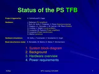
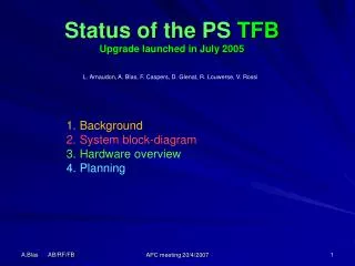
PS TFB Block diagram Green boxes represent devices to be completed APC 30/1/2009
PS TFB Clock distribution PS CB Hardware setup Power + electronics 355-R-017 Kickers + transformers PS SS 97 Water distribution 355-R-017 APC 30/1/2009
PS TFB Pick-up amplifiers J. Belleman BW: 20 kHz – 40 MHz 80 dB dynamic range (compatible with ions) Remotely programmable gain Located in the ring below concrete slab APC 30/1/2009
PS TFB DSPU hardware V. Rossi APC 30/1/2009
PS TFB DSPU firmware Green boxes represent functions to be completed APC 30/1/2009
PS TFB Clock generation J. Sladen 1 GHz DDS Receives the frequency program from the PS central building and outputs the 160*Frev (< 80 MHz). Clock Generator Transforms 10 MHz into 1 GHz APC 30/1/2009
PS TFB Pre-Amplifier • Fast Clipping of the output signal • 0 and 180o outputs • Programmable gain • TFM setup • Local / Remote control • Interface with the PLC control APC 30/1/2009
PS TFB Power Amplifier R. Louwerse [2.5 kHz – 25 MHz], 3kW – 2ms, 800W – CW APC 30/1/2009
PS TFB Impedance matching transformers R. Louwerse Input impedance: 50 Ω Output impedance: 100 Ω [ 2kHz – 40 MHz] 3 kW APC 30/1/2009
PS TFB Kicker F. Caspers, V. Bretin APC 30/1/2009
PS TFB Kicker APC 30/1/2009
PS TFB Power loads 100Ω to 50Ω resistive transition [ DC – 190 MHz] 1.6 kW CW 50 Ω / 30 dB Attenuator [ DC – 1GHz] 1 kW CW APC 30/1/2009
PS TFB PLC Power Control D. Glenat APC 30/1/2009
PS TFB Operation display J. M. Nonglaton APC 30/1/2009
PS TFB Results: Automatic delay • Resolution=0.4ns • Measurement time: 22 us • Maximum jitter : 260 ps • Precision requirement: • 1.1 ns for 10o error at 25 MHz APC 30/1/2009
PS TFB Machine Results Auto Dly + Hilbert The proper functioning of the automatic delay has been tested during an MD on MDPS (22/09/08) with a copy of the SFTPRO beam. The beam transfer function was measured on the 3.5 GeV plateau and on the 14 GeV plateau. If the phase response of all betatron lines can be superimposed, the delay is correct. The parameters of the automatic delay were set at 3.5 GeV for a proper phase response and the measurements made again at 14 GeV proved that the circuit behaved as expected. The measurements made another day at 1.4 GeV gave the same positive results. BTF of a Q+q betatron line APC 30/1/2009
PS TFB Results: Notch Filter APC 30/1/2009
PS TFB Results: Hilbert Filter M= 3 Hilbert Without Notch Filter – set value = 45o With Notch Filter – set value = 45o APC 30/1/2009
PS TFB Results: Hilbert Filter M= 1 Hilbert Without Notch Filter – set value = 45o With Notch Filter – set value = 45o APC 30/1/2009
PS TFB Sensitivity to Q measurement • With the PU in SS98 and the kicker in SS97, the ideal betatron phase lag within the TFB path can be expressed as follow (qH,VЄ [0 , 0.5]): • ΔφB-TFB = -111.6o + (536.4o * q) in the case of no delay for the dephasing (2 PUs!) • ΔφB-TFB = -111.6o + (896.4o * q) in the case of 1TREV delay for the dephasing (m=1 Hilbert) • ΔφB-TFB = -111.6o + (1616.4o * q) in the case of 3TREV delay for the dephasing (m=3 Hilbert) • 9o phase error for an error in q of 0.01 with the m=1 Hilbert • ( <=> 4.5 kHz error in the FFT) One measurement made on LHC25. 11/11/08 The Q measurements are supposed to have a precision of 100ppm Unfortunately during the tests we had a jitter from cycle to cycle The rf clock of the Q measurement doesn’t take into account the loop errors of the RFLL. Is this the explanation? APC 30/1/2009
PS TFB Results 30mm p-p initial H error MDPS 1.4 GeV flat cycle with no Chromaticity and no coupling 23/10/08 PSB MD1 beam 55.1010 p injected (3 turns in R3) Injection error obtained by setting PI.KFA45 to 270 kV instead of 300 kV Inj. error Damping: 20mm/ms @ 1.4 GeV (21mm/ms required for the most demanding case: Pilot beam εn = 0.8μm) Power system used for controlled blow-up (slow extraction) and Q measurement 500 μs/div From M. Martini APC 26/5/2005 APC 30/1/2009
PS TFB Results 30mm p-p initial H error 500 μs/div Zoom top = h position bottom = kick 2μs/div APC 30/1/2009
PS TFB Results MD 11/11/2008 E. Metral With coupling – No TFB Without coupling – No TFB • LHC25 injection plateau at 1.4 GeV with linear H/V coupling (Iskew =-0.3) • Without coupling (Iskew = +0.3) • See logbook for more details (11/11/08) • Last plot taken from a good shot; not always the case (The Betatron phase was set to an empirical fixed value!) Without coupling – With TFB APC 30/1/2009
PS TFB Results MD 11/12/2008 • Q measurement Without coupling – No TFB Only the H plane is excited APC 30/1/2009
PS TFB Conclusion • The MDs on the machine show that the PSTFB fulfills the expected requirements: • Kick efficiency • Automatic delay • Hilbert filter • Remote control of the DSPU and of the Power system • Usage of the power system for the Q measurements and controlled blow-up • Improvements for 2009: • Hardware • 2 fully loaded DSPU modules instead of the single beta version. • 2nd input on the DSPU with a serial delay for the 2nd PU. ( -> lower sensitivity to Q value) • 3rd and 4th inputs on the DSPU for the PU SUM signals (normalization of the Delta signal) • DSPU input impedance varies with the input attenuation (52 -> 72Ω) • Install a driver for a better compatibility with the Q measurement excitation • Firmware • Notch filter could be modified for a more suitable phase response • Q-to-Hilbert-phase LUT should be adapted to take into account the phase errors of the Hilbert (with respect to the command) together with the response of the Notch. • Software • Q (h and V) measured along the cycle (0.01 precision) and value sent to a GFAS (PA.GSTFBH and PA.GSTFBV) • PU control knob to be created (Automatic gain as a function of peak beam intensity ?) • Other • Q measurement (rev clock used for the sampling of the beam signal precise enough ?) APC 30/1/2009