Download
1 / 80
850 likes | 975 Views
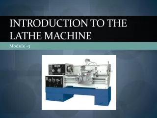
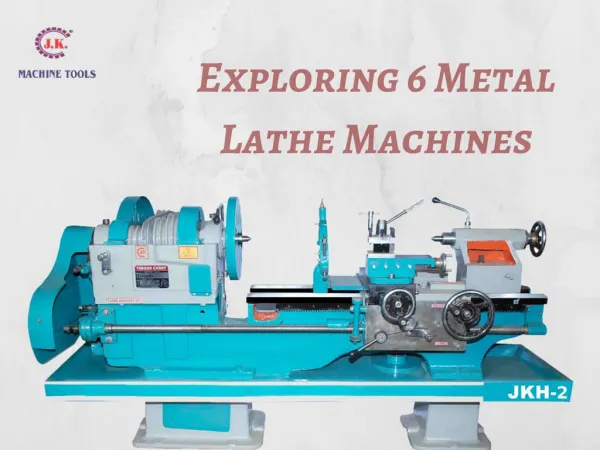
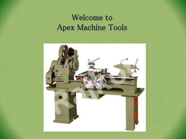
Session 4 Constructional features of centre lathe Operations performed on lathe machine Methods of mounting of jobs and cutting tools specifications. Constructional features of centre lathe

E N D
Session 4 • Constructional features of centre lathe • Operations performed on lathe machine • Methods of mounting of jobs and cutting tools • specifications
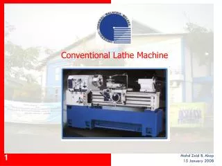
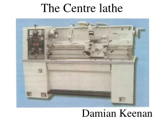
Constructional features of centre lathe • The head stock is towards the left-end on the bed and is fixed to it, which houses the power source. • The spindle is hollow and should be sufficiently rigid to provide accurate rotary motion, and maintain perfect alignment with the lathe axis. • A live centre fits into the morse taper in the spindle hole for the purpose of locating the workpiece axis. • The main gear box provides necessary spindle speeds, considering range of materials to be turned in the lathe. • The head stock also houses the feed gear box to provide the various feed rates and thread cutting ranges. • The tail stock is towards the right end on the bed. • This provides a tail stock spindle for the purpose of locating the long components by the use of centres.
Constructional features of centre lathe • The tail stock is movable on the inner guide ways provided on the bed to accommodate the different lengths of workpieces. • It also serves the purpose of holding tools, such as centre drill, twist drill, reamer etc. • The carriage which provides the necessary longitudinal motion to the cutting tool to generate the necessary surfaces. • This also houses the cross slide for giving the motion to the cutting tool, in a direction perpendicular to the axis of rotation. • Compound rest, which provides an auxillary slide to get the necessary special motion for specific surfae generations. • Tool post, which allows mounting of the cutting tool. • The motion from the spindle motor is communicated to the carriage through a lead screw. • Engagement of lead screw with the carriage is through the use of a half nut.
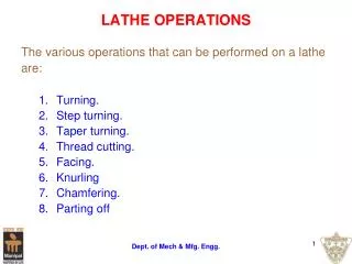
Lathe Operations • During the process cycle, a variety of operations may be performed to the work piece to yield the desired part shape. • These operations may be classified as external or internal. • External operations modify the outer diameter of the work piece, while internal operations modify the inner diameter. • The following operations are each defined by the type of cutter used and the path of that cutter to remove material from the work piece.
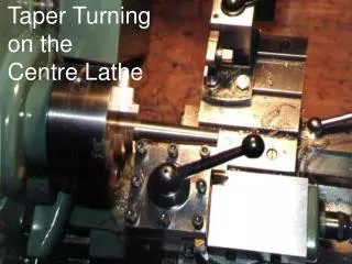
Turning : • A single-point turning tool moves axially, along the side of the work piece, removing material to form different features, including steps, tapers, chamfers, and contours. • These features are typically machined at a small radial depth of cut and multiple passes are made until the end diameter is reached. • Depth of cut of 1 mm will reduce diameter by 2 mm
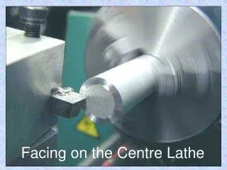
Facing - • A single-point turning tool moves radially, along the end of the workpiece, removing a thin layer of material to provide a smooth flat surface. • The depth of the face, typically very small, may be machined in a single pass or may be reached by machining at a smaller axial depth of cut and making multiple passes.
Feed: in direction perpendicular to work piece axis Depth of Cut: in direction parallel to work piece axis
3. Grooving - • A single-point turning tool moves radially, into the side of the workpiece, cutting a groove equal in width to the cutting tool. • Multiple cuts can be made to form grooves larger than the tool width and special form tools can be used to create grooves of varying geometries.
4.Cut-off (parting) – • Similar to grooving, a single-point cut-off tool moves radially, into the side of the workpiece, and continues until the center or inner diameter of the workpiece is reached, thus parting or cutting off a section of the workpiece.
5. Thread cutting - • A single-point threading tool, typically with a 60 degree pointed nose, moves axially, along the side of the workpiece, cutting threads into the outer surface. • The threads can be cut to a specified length and pitch and may require multiple passes to be formed.
6. Drilling: • An operation in which a drill enters the work piece axially and cuts a hole with a diameter equal to that of the tool. • On a milling machine, an end milling operation is required to produce a hole with a tool smaller than the hole diameter. • A drilling operation typically produces a blind hole, which extends to some depth inside the workpiece, measured to the point made by the tool or to the end of the full diameter portion. • On a milling machine, a hole that extends completely through the workpiece (through hole) can also be drilled.
7. Boring: • An operation in which a boring tool enters the work piece axially and cuts along an internal surface to form different features. • The boring tool is a single-point cutting tool, which can be set to cut the desired diameter by using an adjustable boring head. • Boring is commonly performed after drilling a hole in order to enlarge the diameter or obtain more precise dimensions. • On a turning machine, a variety of features can be formed, including steps, tapers, chamfers, and contours.
These features are typically machined at a small radial depth of cut and multiple passes are made until the end diameter is reached. • For a finish turning operation, the cutting feed is calculated based on the desired surface roughness and the tool nose radius.
8. Reamer: • An operation in which a reamer enters the workpiece axially and enlarges an existing hole to the diameter of the tool. • Reaming removes a minimal amount of material and is often performed after drilling to obtain both a more accurate diameter and a smoother internal finish. • A finish reaming operation will use a slower cutting feed and cutting speed to provide an even better finish
9. Tapping: • An operation in which a tap enters the work piece axially and cuts internal threads into an existing hole. • The existing hole is typically drilled by the required tap drill size that will accommodate the desired tap. • On a milling machine, the threads may be cut to a specified depth inside the hole (bottom tap) or the complete depth of a through hole (through tap).
WORK HOLDING DEVICES & ACCESORIES • Devices that are employed for holding & supporting the work & tool on lathe machine are called accessories. • To machine a component in lathe, it is necessary to see that w/p is held in such a way so as to resist deflection by cutting forces. • There are many work holding devices used in lathe used either for holding w/p or for supporting w/p during machining.
Many different devices, such as chucks, collets, face plates, mandrels, and lathe centers, are used to hold and drive the work while it is being machined on a lathe. • The size and type of work to be machined and the particular operation that needs to be done will determine which work holding device is best for any particular job. • Another consideration is how much accuracy is needed for a job, since some work holding devices are more accurate than others.
Lathe centres: • W/p’s that are relatively long with respect to their diameter are machined between centers. • Most lathe centers have a tapered point with a 60° included angle to fit workplace holes with the same angle. • The work piece is supported between two centers, one in the headstock spindle and one in the tailstock spindle.
Dead centers are solid made of hardened steel with taper on one end so that they will fit into spindle holes. • Other end is ground to 60˚ taper. Tip of this taper is made of tungsten carbide to provide better wear resistance, reduce friction slightly for faster speeds . • Before a centre is placed in position, spindle hole should be carefully wiped clean.
When used in the fixed position, a dead center produces friction between the work piece and center, due to the rotation of the work piece. • Lubrication is therefore required between the center and work piece to prevent friction welding from occurring.
Live centers are designed so that the end that fits into w/p is mounted on ball or roller bearings. • It is free to rotate. • No lubrication is is required.
Top to bottom: MT-2 live center, MT-2 dead center & MT-3 dead center.
Before a w/p can be mounted between centres, 60˚ centre hole must be drilled in each end. • Hole is drilled on drill press or in lathe by holding the cetre in chuck.
Lathe carriers / Driving dogs: • Lathe dogs are cast metal devices used to provide a firm connection between the headstock spindle and the work piece mounted between centers. • This firm connection permits the work piece to be driven at the same speed as the spindle under the strain of cutting. • Carriers are attached to end of w/p by set screw.
When straight-tail dogs are used, the tail bears against a stud projecting from the faceplate
When bent-tail dogs are used, the tail fits into a slot of the driving faceplate.
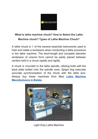
3. Chuck: • It is specialized type of clamp used to hold rotating tool. Used for holding w/p’s of shorter length & larger diameter, irregular shapes which can’t be mounted between centers. • Chuck is attached to spindle(by means of bolts with back plate) which is screwed to spindle nose.
Three jaw universal/ Scroll/ Self centering: • Mainly used for self centering, work for concentric turning, for gripping circular/ hexagonal c.s w/p’s. • The jaws are moved simultaneously with in the chuck by a scroll or spiral-threaded plate. • The jaws are threaded to the scroll disc/ plate. • 3 pinions are fitted radially at back of disc. • Top of pinion carry square slots to accommodate chuck wrench.
For operating any chuck any one of these pinions can be rotated by means of chuck wrench, which in turn revolves scroll disc as result all jaws moves in radially directions inwards/ outwards.
Three jaw chuck in use • The universal scroll chuck can be used to hold and automatically center round or hexagonal workplaces. • Having only three jaws, the chuck cannot be used effectively to hold square, octagonal, or irregular shapes.
b) Four Jaw / Independent: • Mainly used for centering irregular surface w/p ’s & heavy w/p ’s. • These chucks have jaws that can be moved & adjusted independently of each other. • Because of its versatility and capacity for fine adjustment, the independent chuck is commonly used for mounting odd shaped workplaces which must be held with extreme accuracy.
c) Combination Chuck: • A combination chuck combines the features of the independent chuck and the universal scroll chuck and can have either three or four jaws. • The jaws can be moved in unison on a scroll for automatic centering or can be moved individually if desired by separate adjusting screws.