Download
1 / 47
570 likes | 961 Views
Conventional Lathe Machine. Mohd Zaid B. Akop 15 January 2008. FAKULTI KEJURUTERAAN MEKANIKAL UNIVERSITI TEKNIKAL MALAYSIA MELAKA. CONTENTS. Introduction Machine Function Safety Precautions Cutting Tools Toolholders Lathe Operations Speeds & Feeds Tools Geometry.

E N D
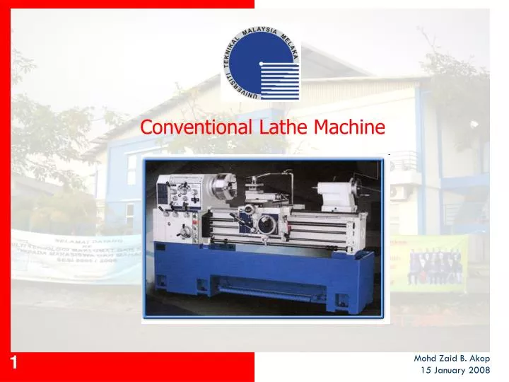
Conventional Lathe Machine Mohd Zaid B. Akop 15 January 2008
FAKULTI KEJURUTERAAN MEKANIKALUNIVERSITI TEKNIKAL MALAYSIA MELAKA CONTENTS Introduction Machine Function Safety Precautions Cutting Tools Toolholders Lathe Operations Speeds & Feeds Tools Geometry
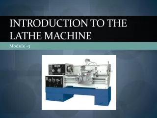
FAKULTI KEJURUTERAAN MEKANIKALUNIVERSITI TEKNIKAL MALAYSIA MELAKA 1. INTRODUCTION Description: • The purpose of a lathe is to rotate a part against a cutting tool, thereby removing metal. It is used for fabricating parts and/or features that have a circular cross section. The spindle is the part of the lathe that rotates. Various work holding attachments such as three jaw chucks, collets, and centers can be held in the spindle. The spindle is driven by an electric motor through a system of belt drives and/or gear trains. Lathe cutting action (Source: Kelmar Associates)
FAKULTI KEJURUTERAAN MEKANIKALUNIVERSITI TEKNIKAL MALAYSIA MELAKA 1. INTRODUCTION-(cont’d) • Spindle speed is controlled by varying the geometry of the drive train. The tailstock can be used to support the end of the workpiece with a center, or to hold tools for drilling, reaming, threading, or cutting tapers. It can be adjusted in position along the ways to accomodate different length workpieces. The ram can be fed along the axis of rotation with the tailstock handwheel. The carriage controls and supports the cutting tool. It consists of: • A saddle that mates with and slides along the ways. • An apron that controls the feed mechanisms. • A cross slide that controls transverse motion of the tool (toward or away from the operator). • A tool compound that adjusts to permit angular tool movement. • A toolpost T-slot that holds the toolpost.
FAKULTI KEJURUTERAAN MEKANIKALUNIVERSITI TEKNIKAL MALAYSIA MELAKA 1. INTRODUCTION-(cont’d) Lathe Machine
FAKULTI KEJURUTERAAN MEKANIKALUNIVERSITI TEKNIKAL MALAYSIA MELAKA 1. INTRODUCTION-(cont’d) Types of Lathes: The engine lathe has kept pace with technological changes in order to increase productivity and improve part quality. The most common engine lathes are: The Engine Lathe – the accuracy of work produced is controlled by the operator. An experienced operator will be able to produce work to within 0.02 mm of accuracy. The Engine Lathe with Digital Readout – it helps to improve the accuracy and performance of a lathe machine. Accuracy is up to 0.002 mm. The Conventional/Programmable Lathe – it is equipped with digital readout (DR) and limited programming features. DR shows the location of cutting tool and X and Z workpiece dimensions. The Computer-Numerically Controlled Lathe (CNC Lathe) – all movements are CNC controlled. Specially designed for production work that requires great precision and high productivity.
FAKULTI KEJURUTERAAN MEKANIKALUNIVERSITI TEKNIKAL MALAYSIA MELAKA 2. MACHINE FUNCTION Main Functions of a Lathe Machine: The main function of a lathe machine is to provide a means of rotating a workpiece against a cutting tool, thereby removing metal. All lathes have the same 3 basic functions: A support for the lathe accessories or the workpiece. A way of holding and revolving the workpiece. A means of holding and moving the cutting tools. Headstock - headstock supports spindle which rotates on ‘Zero Precision’ tapered roller bearings. Work holders are mounted on spindle nose. Chuck - chuck is mounted on spindle nose. Adjustable jaws permit holding of larger diameter workpieces.
FAKULTI KEJURUTERAAN MEKANIKALUNIVERSITI TEKNIKAL MALAYSIA MELAKA 2. MACHINE FUNCTION-(cont’d) Tailstock - tailstock center supports right end of work held ‘between centers’. It can be offset to cut tapers, lock in any position along lathe bed, and has hand wheel feed for tailstock tools. Apron - apron controls are centrally grouped with selector lever for power longitudinal and cross feeds, friction clutch for engaging feeds, half nut lever for thread cutting, and hand wheel for hand traverse of carriage.
FAKULTI KEJURUTERAAN MEKANIKALUNIVERSITI TEKNIKAL MALAYSIA MELAKA 3. SAFETY PRECAUTIONS General Turning: Wear approved safety goggles. Confirm that all guards are in place. Before starting the lathe, turn the spindle by hand to insure that it turns freely. If the spindle is locked in a stationary position with the back-gear lever as well as the bull-gear pin, release one of these devices for the desired kind of drive and speed. Stop the machine to make adjustment. Stop the machine if you need to make measurement. Stop the machine to remove chips. Do not remove them with the hands - always use a brush or stick. Stop the machine for oiling. Always stop the machine when adjusting the tool in the tool post.
FAKULTI KEJURUTERAAN MEKANIKALUNIVERSITI TEKNIKAL MALAYSIA MELAKA 3. SAFETY PRECAUTIONS-(cont’d) General Turning: Keep the machine clear of long chips, rags, and unnecessary hand tools. Use the right type of cutting tool for the job. Adjust the feed, speed, and depth of cut according to the size and type of metal. Turning Between Centers: Be sure that the tailstock and the tailstock ladle are locked securely. When available, use a safety dog to drive the work piece. Select the smallest dog which will do the job and clamp it tightly. Lubricate the tailstock dead center properly and frequently. Always cut toward the headstock whenever possible. Before starting the power feed, make certain at the carriage has sufficient free travel to complete the cut without running into the lathe dog.
FAKULTI KEJURUTERAAN MEKANIKALUNIVERSITI TEKNIKAL MALAYSIA MELAKA 3. SAFETY PRECAUTIONS-(cont’d) Turning Work in Chuck: Place a board under the chuck when mounting it or removing it from the spindle. Keep the fingers clear. Be sure that the chuck is mounted tightly to the spindle. Be sure that the work is mounted tightly in the chuck. Always remove the chuck wrench or key from the chuck immediately after using it. Turn the chuck one complete revolution by hand after the work is mounted to see that it clears the carriage and the ways. Never allow the cutting tool or tool holder to come into contact with the revolving chuck jaws.
FAKULTI KEJURUTERAAN MEKANIKALUNIVERSITI TEKNIKAL MALAYSIA MELAKA 3. SAFETY PRECAUTIONS-(cont’d) Turning Work in Faceplate: 23. Be sure the faceplate is secured tightly to the lathe spindle. 24. Use the shortest bolts and clamps possible for clamping work to the faceplate, and clamp the work securely. The clamps should be supported at the outer ends and should be parallel to the faceplate. 25. Use a counterweight, if necessary, to balance an off-center work piece. 26. Before starting the machine, turn the work one complete revolution by hand to see that it clears the carriage and the ways.
FAKULTI KEJURUTERAAN MEKANIKALUNIVERSITI TEKNIKAL MALAYSIA MELAKA 4. CUTTING TOOLS Lathe Cutting Tools: Tool bits - types of tool bits include right and left hand turning tools, facing tools, cutoff tools and threading tools.
FAKULTI KEJURUTERAAN MEKANIKALUNIVERSITI TEKNIKAL MALAYSIA MELAKA 4. CUTTING TOOLS-(cont’d) Common cuts made by various cutting tools:
FAKULTI KEJURUTERAAN MEKANIKALUNIVERSITI TEKNIKAL MALAYSIA MELAKA 4. CUTTING TOOLS-(cont’d) Carbide tipped: These tool are resharpened as needed, using special silicon carbide or diamond grinding wheel. • Indexable throwaway inserts: • Made of carbide, ceramic and diamond • When the initial cutting edge became dulled, rotate to the next cutting edge, reclamp and continue cutting without any change of tool holder position. • Regrinding – generally more costly than replacing them. Discarded after all cutting edges become dulled
FAKULTI KEJURUTERAAN MEKANIKALUNIVERSITI TEKNIKAL MALAYSIA MELAKA 4. CUTTING TOOLS-(cont’d) Standard shapes for indexable throwaway insert cutter
FAKULTI KEJURUTERAAN MEKANIKALUNIVERSITI TEKNIKAL MALAYSIA MELAKA 4. CUTTING TOOLS-(cont’d) • Cutting Tool Materials: • Cutting tools for metalworking are made of high speed steel, cast alloys and cemented carbide. • Also made of ceramic and diamonds for special purposes. • Cutting tool must be made of material with suitable properties: • Must have sufficient hardness to cut other materials • Must be capable of retaining hardness at high temperatures which are produced at the cutting edge. • Must have good wear resistance • Must posses sufficient toughness to prevent chipping or fracturing.
FAKULTI KEJURUTERAAN MEKANIKALUNIVERSITI TEKNIKAL MALAYSIA MELAKA 5. TOOLHOLDERS Types of toolholder Straight shank toolholder -hold tool bit parallel to the base of the toolholder shank -Intended for holding carbide tipped tool bit also cast alloy bit Throwaway insert toolholder -Used to hold a carbide/ceramic cutting tool and chip breaker -Many types throwaway insert toolholder are made to hold different insert.
FAKULTI KEJURUTERAAN MEKANIKALUNIVERSITI TEKNIKAL MALAYSIA MELAKA 5. TOOLHOLDERS-(cont’d) Types of toolholder Boring toolholders -Used for boring operations using lathe machine Cutoff toolholders -Used for holding cutoff tool. -Used for cutting grooves, Cutting off stock. Threading toolholders -Used for holding threading tool. Knurling tool -Used for performing knurling operations
FAKULTI KEJURUTERAAN MEKANIKALUNIVERSITI TEKNIKAL MALAYSIA MELAKA 6. LATHE OPERATIONS • INSTALLING A CUTTING TOOL • Lathe cutting tools are held by tool holders. To install a tool, first clean the holder, then tighten the bolts. [Video1] • The tool post is secured to the compound with a T-bolt. The tool holder is secured to the tool post using a quick release lever. [Video2] • POSITIONING THE TOOL • First, loosen the bolts securing the compound to the saddle. Then rotate the compound to the desired angle referencing the dial indicator at the base of the compound. Retighten the bolts. Now the tool can be hand fed along the desired angle. No power feed is available for the compound. If a fine finish is required, use both hands to achieve a smoother feed rate. • The cross slide and compound have a micrometer dial to allow accurate positioning, but the saddle doesn't. To position the saddle accurately, you may use a dial indicator mounted to the saddle.
FAKULTI KEJURUTERAAN MEKANIKALUNIVERSITI TEKNIKAL MALAYSIA MELAKA 6. LATHE OPERATIONS-(cont’d) TURNING The lathe can be used to reduce the diameter of a part to a desired dimension. First, clamp the part securely in a lathe chuck. The part should not extend more that three times its diameter. Then install a roughing or finishing tool (whichever is appropriate). If you're feeding the saddle toward the headstock (as in the clip below) use a right-hand turning tool. Move the tool off the part by backing the carriage up with the carriage handwheel, then use the cross feed to set the desired depth of cut. In the clip below, a finish cut is made using the power feed for a smoother finish. Remember that for each thousandth depth of cut, the work diameter is reduced by two thousandths. [Video3]
FAKULTI KEJURUTERAAN MEKANIKALUNIVERSITI TEKNIKAL MALAYSIA MELAKA 6. LATHE OPERATIONS-(cont’d) FACING A lathe can be used to create a smooth, flat, face very accurately perpendicular to the axis of a cylindrical part. First, clamp the part securely in a lathe chuck [Video4]. Then, install a facing tool. Bring the tool approximately into position, but slightly off of the part. Always turn the spindle by hand before turning it on. This ensures that no parts interfere with the rotation of the spindle. [Video5] Move the tool outside the part and adjust the saddle to take the desired depth of cut. Then, feed the tool across the face with the cross slide. The following clip shows a roughing cut being made; about 50 thousandths are being removed in one pass [Video6]. If a finer finish is required, take just a few thousandths on the final cut and use the power feed. Be careful clearing the ribbon-like chips; They are very sharp. Do not clear the chips while the spindle is turning. After facing, there is a very sharp edge on the part. Break the edge with a file. [Video7]
FAKULTI KEJURUTERAAN MEKANIKALUNIVERSITI TEKNIKAL MALAYSIA MELAKA 6. LATHE OPERATIONS-(cont’d) • PARTING • A parting tool is deeper and narrower than a turning tool. It is designed for making narrow grooves and for cutting off parts. When a parting tool is installed, ensure that it hangs over the tool holder enough that the holder will clear the w/piece. • Ensure that the parting tool is perpendicular to the axis of rotation and that the tip is the same height as the center of the part. A good way to do this is to hold the tool against the face of the part. Set the height of the tool, lay it flat against the face of the part, then lock the tool in place [Video8]. When the cut is deep, the side of the part can rub against sides of the groove, so it’s especially important to apply cutting fluid. In this clip, a part is cut off from a piece of stock. [Video9]
FAKULTI KEJURUTERAAN MEKANIKALUNIVERSITI TEKNIKAL MALAYSIA MELAKA 6. LATHE OPERATIONS-(cont’d) • DRILLING • A lathe also be used to drill hole accurately concentric with the centerline of a cylindrical part. First, install a drill chuck into the tail stock. Make certain that the back of the drill chuck seats properly in the tail stock. Draw the jaws of the chuck and tap the chuck in place with a soft hammer. [Video10] • Move the saddle forward to make room for the tailstock. Move the tailstock into position and lock the it in place. Before starting the machine turn the spindle by hand. Always use a centerdrill to start the hole. You should use cutting fluid with the center drill [Video11]. Always drill past the beginning of the taper to create a funnel to guide the bit in. In this clip, a hole is drilled with a drill bit. [Video12]
FAKULTI KEJURUTERAAN MEKANIKALUNIVERSITI TEKNIKAL MALAYSIA MELAKA 6. LATHE OPERATIONS-(cont’d) BORING Is an operation in which a hole is enlarged with a single point cutting tool. A boring bar is used to support the cutting tool as it extends into the hole. Because of the extension of the boring bar, the tool is supported less rigidity and is more likely to chatter. This can be corrected by using slower spindle speeds or grinding a smaller radius on the nose of the tool. Boring on a Lathe (www.eng.mu.edu)
FAKULTI KEJURUTERAAN MEKANIKALUNIVERSITI TEKNIKAL MALAYSIA MELAKA 6. LATHE OPERATIONS-(cont’d) SINGLE POINT THREAD TURNING External threads can be cut with a die and internal thread can be cut with a tap. But for some diameter, no die or tap available. In these cases, threads can be cut on a lathe. A special cutting tool should be used, typically with 60 degree nose angle. To form threads with a specified number of thread per inch/mm, the spindle is mechanically coupled to the carriage lead screw. Threading on a Lathe (www.phantasmechanics.com)
FAKULTI KEJURUTERAAN MEKANIKALUNIVERSITI TEKNIKAL MALAYSIA MELAKA 7. SPEEDS & FEEDS • CUTTING SPEED FOR LATHE WORK • Correct cutting speeds is important for good tool life and efficient machining. • For lathe work, cutting speed refers to the rate in meter per minute at which the surface of the workpiece moves past the cutting tool. • Condition that affect cutting speed: • Kind of material being cut • Kind of material the cutting tool is made • Shape of the cutting tool being used • Rigidity of the workpiece • Rigidity of the machine • Kind of cutting fluid being used
FAKULTI KEJURUTERAAN MEKANIKALUNIVERSITI TEKNIKAL MALAYSIA MELAKA 7. SPEEDS & FEEDS-(cont’d)
FAKULTI KEJURUTERAAN MEKANIKALUNIVERSITI TEKNIKAL MALAYSIA MELAKA 7. SPEEDS & FEEDS-(cont’d) Cutting speeds are determined using the formula: rpm = v / (D x ) where rpm = revolutions per minute v = cutting speed, in meter per minute (mpm) D = diameter of workpiece = 3.14 Example 1: If the cutting speed is 12 mpm for a certain alloy steel and workpiece is 5cm in diameter, find the rpm. rpm = v / (D x) rpm = 12 / (5x10-2 x 3.14) rpm = 76
FAKULTI KEJURUTERAAN MEKANIKALUNIVERSITI TEKNIKAL MALAYSIA MELAKA 7. SPEEDS & FEEDS-(cont’d) Example 2: What rpm should be used for a heavy cut of 30.5 mpm on a piece of low carbon steel of 50.8 mm diameter. rpm = v / (D x) rpm = 30.5 / (50.8x10-3 x 3.14) rpm = 191
FAKULTI KEJURUTERAAN MEKANIKALUNIVERSITI TEKNIKAL MALAYSIA MELAKA 7. SPEEDS & FEEDS-(cont’d) • CUTTING FEEDS FOR LATHE WORK • Feeds is the distance a cutting tool advances per revolution. • Feeds are expressed in milimeters per revolution of the spindle. • Feeds are determined by the formula: T = L / (f x N) where T = time, in minutes L = length of cut, in milimeters f = feed, in milimeters per revolution (mmpr) N = lathe spindle speed, in rpm
FAKULTI KEJURUTERAAN MEKANIKALUNIVERSITI TEKNIKAL MALAYSIA MELAKA 7. SPEEDS & FEEDS-(cont’d) Example: A shaft is being turned at 130 rpm and feed 0.5 mmpr. If the length of cut is 100 mm, calculate the time required to make the cut. T = L / (f x N) T = 100 mm / (0.5 mmpr x 130 rpm) T = 1.54 min
FAKULTI KEJURUTERAAN MEKANIKALUNIVERSITI TEKNIKAL MALAYSIA MELAKA 7. SPEEDS & FEEDS-(cont’d) TURNING OPERATION
FAKULTI KEJURUTERAAN MEKANIKALUNIVERSITI TEKNIKAL MALAYSIA MELAKA 7. SPEEDS & FEEDS-(cont’d) • The rotational speed in turning is related, to the desired cutting speed at the surface of the cylindrical work piece by the equation N (rpm) = v / (Do x ) where N = rotational speed , rev/min v = cutting speed, (m/min) Do = original diameter of the part, (m) • The turning operation reduces the diameter of the work from Do to final diameter Df . The change in diameter is determined by the depth of cut d: Do – Df = 2d • The feed in turning is generally expressed in mm/rev. This feed can be converted to a linear travel in mm/min by the formula fr = Nf where fr= feed rate in mm/min and f = mm/rev and N = rotational speed, rev/min.
FAKULTI KEJURUTERAAN MEKANIKALUNIVERSITI TEKNIKAL MALAYSIA MELAKA 7. SPEEDS & FEEDS-(cont’d) • The time to machine from one end of a cylindrical workpart to the other is given by • Tm = L/ fr • where Tm = time of actual machining, minute • L= length of the cylindrical work part in mm • The volumetric rate of material removal can be most conveniently determined by the following equation: MRR = v f d where MRR = material removal rate (mm3/min)
FAKULTI KEJURUTERAAN MEKANIKALUNIVERSITI TEKNIKAL MALAYSIA MELAKA 7. SPEEDS & FEEDS-(cont’d) Example: A 60 mm long, 50 mm diameter aluminum rod being reduced in diameter to 49 mm by turning on a lathe machine. Find material removal rate (MRR) if cutting speed 70 m/min and time to machine 2 min. N (rpm) = v / (Do x ) = 70 (m/min) / [50x10-3 (m) x 3.14] = 445.9 rev/min Tm = L / fr fr = L / Tm = 60 mm / 2 min = 30 mm/min
FAKULTI KEJURUTERAAN MEKANIKALUNIVERSITI TEKNIKAL MALAYSIA MELAKA 7. SPEEDS & FEEDS-(cont’d) fr = Nf f = fr / N (f = feed in mm/rev) = (30 mm/min) / (445.6 rev/min) = 0.0673 mm/rev determined by the depth of cut d: Do – Df = 2d d = (Do – Df ) / 2 = (50 – 49) / 2 = 0.5 mm MRR = v f d = 70 m/min x 0.0673 mm/rev x 0.5 mm x 1000 = 2355.5 mm3 /min
FAKULTI KEJURUTERAAN MEKANIKALUNIVERSITI TEKNIKAL MALAYSIA MELAKA 8. TOOL GEOMETRY • TOOL GEOMETRY • A cutting tool must posses a shape that is suited to the machining operation. Important way to classify cutting tools is according to the machining process. We have turning tools, cutoff tools, drill bit, reamers, tap and many other cutting tool that are name for operation. • Cutting tools can be divided into two categories: Single point tools and multiple cutting edge tools.
FAKULTI KEJURUTERAAN MEKANIKALUNIVERSITI TEKNIKAL MALAYSIA MELAKA 8. TOOL GEOMETRY-(cont’d) Cutting Tool Terminology: (Source: R. Kibbe, 2006)
FAKULTI KEJURUTERAAN MEKANIKALUNIVERSITI TEKNIKAL MALAYSIA MELAKA 8. TOOL GEOMETRY-(cont’d) • Cutting Tool Terminology: • The tool shank is that part held by the toolholder. • Back rake is important to smooth chip flow, needed for uniform chip and good finish. • The side rake directs the chip flow away from the point of cut. • The end relief angle prevents the front edge of the tool from rubbing on the work. • The side relief angle provides for cutting action by allowing the tool to feed into the work material. • The side cutting edge angle (SCEA) directs the cutting forces. Also helps to direct the chip flow away from workpiece. • The nose radius is important in controlling surface finish. It will vary according to the finish required.
FAKULTI KEJURUTERAAN MEKANIKALUNIVERSITI TEKNIKAL MALAYSIA MELAKA 8. TOOL GEOMETRY-(cont’d) • MECHANICS OF BASIC MACHINING OPERATION • The important parameter involve • The thickness of the uncut layer (t1) • The thickness of the chip produced (t2) • The inclination of the chip-tool interface with respect to the cutting velocity (the face of the tool in contact with the chip known as rake face) i.e the rake angle(α) • The relative velocity of the • workpiece and the tool (v)
FAKULTI KEJURUTERAAN MEKANIKALUNIVERSITI TEKNIKAL MALAYSIA MELAKA 8. TOOL GEOMETRY-(cont’d) EFFECT OF RAKE ANGLE The performance of a cutting tool is markedly affected by its rake angle as follows: 1. Strength of tool and heat conduction a. A tool with large rake angle is weak so that the point may break off. Also the heat will not be conducted away from the point of tool effectively. b. The shape with negative rake angle results is stronger tool with better heat conductivity. 2. Effect on cutting force. As the rake angle is decreased, the shear plane angle Ф will be decreased and for the same depth of cut, the extent of the shear plane will be increased so that the cutting force will be increased.
FAKULTI KEJURUTERAAN MEKANIKALUNIVERSITI TEKNIKAL MALAYSIA MELAKA 8. TOOL GEOMETRY-(cont’d) • TWO METHOD OF DETERMINING THE SHEAR ANGLE • Mathematical Analysis • The early study in determining the shear angle Ф mathematically was done by Ernst and Merchant based on the model of orthogonal cutting. • Experiment technique • Using quick stop device to • freeze the tool on the • workpiece and the cutting • zone is captured by • photomicrography
FAKULTI KEJURUTERAAN MEKANIKALUNIVERSITI TEKNIKAL MALAYSIA MELAKA 8. TOOL GEOMETRY-(cont’d) • CHIP BREAKER • Chip disposal is a problem that is often encountered in turning and other continuous operations. Long, stringy chips are often generated, especially when turning ductile materials at high speeds. These chips cause a hazard to the machine operator and to the workpart finish and they interfere with automatic operation of the turning process. • Chip breakers are frequently used with a single point tools to force the chip to curl more tightly than they would naturally be inclined to do, thus causing them to fracture. Two principal forms of chip breaker design are commonly used on single point turning tools.
FAKULTI KEJURUTERAAN MEKANIKALUNIVERSITI TEKNIKAL MALAYSIA MELAKA 8. TOOL GEOMETRY-(cont’d) • 2 Types of Chip Breakers: • Groove type chipbreaker designed into the cutting tool itself. • Obstruction type chip breaker designed as an additional device on the rake face of tool. The chip breaker distance can be adjusted in the obstruction type device for different cutting conditions.
FAKULTI KEJURUTERAAN MEKANIKALUNIVERSITI TEKNIKAL MALAYSIA MELAKA THE END THANK YOU
FAKULTI KEJURUTERAAN MEKANIKALUNIVERSITI TEKNIKAL MALAYSIA MELAKA HUreyyy…..QUIZZ time….. A 6-in. long, ½-in. diameter 304 stainless steel rod is being reduced in diameter to 0.480 in. by turning on a lathe. The spindle rotates at N = 400 rpm, and the tool is travelling at an axial speed of 8 in./min. Calculate the : 1) cutting speed, 2) Material removal rate, 3) time to cut, 4) power dissipated and 5) cutting forces. GOOD LUCK!!!!!!