Download
1 / 64
660 likes | 1.17k Views
Computer Organization EECC 550. Week 1 Week 2 Week 3 Week 4 Week 5 Week 6 Week 7 Week 8 Week 9 Week 10 Week 11. Introduction: Modern Computer Design Levels, Components, Technology Trends, Register Transfer Notation (RTN). [Chapters 1, 2]

E N D
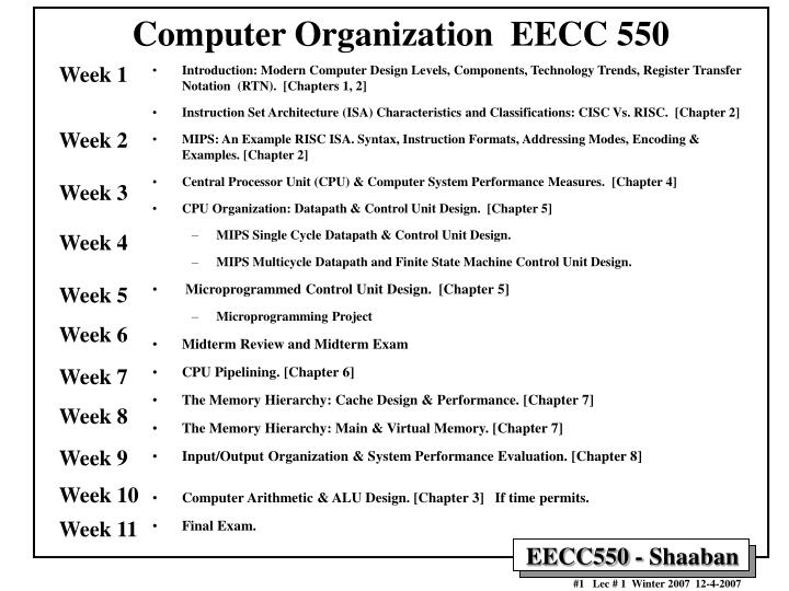
Computer Organization EECC 550 Week 1 Week 2 Week 3 Week 4 Week 5 Week 6 Week 7 Week 8 Week 9 Week 10 Week 11 • Introduction: Modern Computer Design Levels, Components, Technology Trends, Register Transfer Notation (RTN). [Chapters 1, 2] • Instruction Set Architecture (ISA) Characteristics and Classifications: CISC Vs. RISC. [Chapter 2] • MIPS: An Example RISC ISA. Syntax, Instruction Formats, Addressing Modes, Encoding & Examples. [Chapter 2] • Central Processor Unit (CPU) & Computer System Performance Measures. [Chapter 4] • CPU Organization: Datapath & Control Unit Design. [Chapter 5] • MIPS Single Cycle Datapath & Control Unit Design. • MIPS Multicycle Datapath and Finite State Machine Control Unit Design. • Microprogrammed Control Unit Design. [Chapter 5] • Microprogramming Project • Midterm Review and Midterm Exam • CPU Pipelining. [Chapter 6] • The Memory Hierarchy: Cache Design & Performance. [Chapter 7] • The Memory Hierarchy: Main & Virtual Memory. [Chapter 7] • Input/Output Organization & System Performance Evaluation. [Chapter 8] • Computer Arithmetic & ALU Design. [Chapter 3] If time permits. • Final Exam.
Computing System History/Trends + Instruction Set Architecture (ISA) Fundamentals • Computing Element Choices: • Computing Element Programmability • Spatial vs. Temporal Computing • Main Processor Types/Applications • General Purpose Processor Generations • The Von Neumann Computer Model • CPU Organization (Design) • Recent Trends in Computer Design/performance • Hierarchy of Computer Architecture • Hardware Description: Register Transfer Notation (RTN) • Computer Architecture Vs. Computer Organization • Instruction Set Architecture (ISA): • Definition and purpose • ISA Specification Requirements • Main General Types of Instructions • ISA Types and characteristics • Typical ISA Addressing Modes • Instruction Set Encoding • Instruction Set Architecture Tradeoffs • Complex Instruction Set Computer (CISC) • Reduced Instruction Set Computer (RISC) • Evolution of Instruction Set Architectures (Chapters 1, 2)
Computing Element Choices • General Purpose Processors (GPPs): Intended for general purpose computing (desktops, servers, clusters..) • Application-Specific Processors (ASPs): Processors with ISAs and architectural features tailored towards specific application domains • E.g Digital Signal Processors (DSPs), Network Processors (NPs), Media Processors, Graphics Processing Units (GPUs), Vector Processors??? ... • Co-Processors: A hardware (hardwired) implementation of specific algorithms with limited programming interface (augment GPPs or ASPs) • Configurable Hardware: • Field Programmable Gate Arrays (FPGAs) • Configurable array of simple processing elements • Application Specific Integrated Circuits (ASICs): A custom VLSI hardware solution for a specific computational task • The choice of one or more depends on a number of factors including: - Type and complexity of computational algorithm (general purpose vs. Specialized) - Desired level of flexibility/ - Performance requirements programmability - Development cost/time - System cost - Power requirements - Real-time constrains The main goal of this course is the study of fundamental design techniques for General Purpose Processors
Computing Element Choices The main goal of this course is the study of fundamental design techniques for General Purpose Processors General Purpose Processors (GPPs): Flexibility Processor : Programmable computing element that runs programs written using a pre-defined set of instructions Application-Specific Processors (ASPs) Programmability / Configurable Hardware Selection Factors: Co-Processors - Type and complexity of computational algorithms (general purpose vs. Specialized) - Desired level of flexibility - Performance - Development cost - System cost - Power requirements - Real-time constrains Application Specific Integrated Circuits (ASICs) Specialization , Development cost/time Performance/Chip Area/Watt (Computational Efficiency) Performance
Computes one function (e.g. FP-multiply, divider, DCT) Function defined at fabrication time e.g hardware (ASICs) Parameterizable Hardware: Performs limited “set” of functions Computing Element Choices: Computing Element Programmability (Hardware) Software (Processor) Fixed Function: Programmable: • Computes “any” computable function (e.g. Processors) • Function defined after fabrication e.g. Co-Processors Processor = Programmable computing element that runs programs written using pre-defined instructions
Computing Element Choices: Spatial vs. Temporal Computing Spatial Temporal (using software/program running on a processor) (using hardware) Defined by fixedfunctionality and connectivity of hardware elements Hardware Block Diagram Processor Instructions (Program) Processor = Programmable computing element that runs programs written using a pre-defined set of instructions
Main Processor Types/Applications The main goal of this course is the study of fundamental design techniques for General Purpose Processors • General Purpose Computing & General Purpose Processors (GPPs) • High performance: In general, faster is always better. • RISC or CISC: Intel P4, IBM Power4, SPARC, PowerPC, MIPS ... • Used for general purpose software • End-user programmable • Real-time performance may not be fully predictable (due to dynamic arch. features) • Heavy weight, multi-tasking OS - Windows, UNIX • Normally, low cost and power not a requirement (changing) • Servers, Workstations, Desktops (PC’s), Notebooks, Clusters … • Embedded Processing: Embedded processors and processor cores • Cost, power code-size and real-time requirements and constraints • Once real-time constraints are met, a faster processor may not be better • e.g: Intel XScale, ARM, 486SX, Hitachi SH7000, NEC V800... • Often require Digital signal processing (DSP) support or other application-specific support (e.g network, media processing) • Single or few specialized programs – known at system design time • Not end-user programmable • Real-time performance must be fully predictable (avoid dynamic arch. features) • Lightweight, often realtime OS or no OS • Examples: Cellular phones, consumer electronics .. … • Microcontrollers • Extremely code size/cost/power sensitive • Single program • Small word size - 8 bit common • Usually no OS • Highest volume processors by far • Examples: Control systems, Automobiles, industrial control, thermostats, ... Increasing Cost/Complexity Increasing volume Processor = Programmable computing element that runs programs written using pre-defined instructions Examples of Application-Specific Processors (ASPs)
The Processor Design Space Application specific architectures for performance Embedded processors Microprocessors GPPs Real-time constraints Specialized applications Low power/cost constraints Performance is everything & Software rules Performance Microcontrollers The main goal of this course is the study of fundamental design techniques for General Purpose Processors Cost is everything Chip Area, Power complexity Processor Cost Processor = Programmable computing element that runs programs written using a pre-defined set of instructions
General Purpose Processor/Computer System Generations Classified according to implementation technology: • The First Generation, 1946-59: Vacuum Tubes, Relays, Mercury Delay Lines: • ENIAC (Electronic Numerical Integrator and Computer): First electronic computer, 18000 vacuum tubes, 1500 relays, 5000 additions/sec (1944). • First stored program computer: EDSAC (Electronic Delay Storage Automatic Calculator), 1949. • The Second Generation, 1959-64: Discrete Transistors. • e.g. IBM Main frames • The Third Generation, 1964-75: Small and Medium-Scale Integrated (MSI) Circuits. • e.g Main frames (IBM 360) , mini computers (DEC PDP-8, PDP-11). • The Fourth Generation, 1975-Present: The Microcomputer. VLSI-based Microprocessors (single-chip processor) • First microprocessor: Intel’s 4-bit 4004 (2300 transistors), 1970. • Personal Computer (PCs), laptops, PDAs, servers, clusters … • Reduced Instruction Set Computer (RISC) 1984 Common factor among all generations: All target the The Von Neumann Computer Model or paradigm
- Control Input Memory (instructions, data) Datapath registers ALU, buses Output CPU Computer System I/O Devices The Von Neumann Computer Model • Partitioning of the programmable computing engine into components: • Central Processing Unit (CPU):Control Unit (instruction decode , sequencing of operations), Datapath (registers, arithmetic and logic unit, connections, buses …). • Memory: Instruction (program) and operand (data) storage. • Input/Output (I/O) sub-system: I/O bus, interfaces, devices. • The stored program concept: Instructions from an instruction set are fetched from a common memory and executed one at a time AKA Program Counter (PC) Based Architecture The Program Counter (PC) points to next instruction to be processed Major CPU Performance Limitation: The Von Neumann computing model implies sequential execution one instruction at a time Another Performance Limitation: Separation of CPU and memory (The Von Neumann memory bottleneck)
Instruction Fetch Instruction Decode Operand Fetch Execute Result Store Next Instruction Generic CPU Machine Instruction Processing Steps (Implied by The Von Neumann Computer Model) Obtain instruction from program storage (memory) The Program Counter (PC) points to next instruction to be processed Determine required actions and instruction size Locate and obtain operand data Compute result value or status Deposit results in storage for later use Determine successor or next instruction (i.e Update PC to fetch next instruction to be processed) Major CPU Performance Limitation: The Von Neumann computing model implies sequential execution one instruction at a time
Five classic components of all computers: 1. Control Unit; 2. Datapath; 3. Memory; 4. Input; 5. Output } Processor Hardware Components of Computer Systems } I/O Central Processing Unit (CPU) Keyboard, Mouse, etc. Computer Processor (active) Memory (passive) (where programs, data live when running) Devices Input Control Unit I/O Disk Datapath Output Display, Printer, etc.
CPU Organization (Design) Components & their connections needed by ISA instructions • Datapath Design: • Capabilities & performance characteristics of principal Functional Units (FUs) needed by ISA instructions • (e.g., Registers, ALU, Shifters, Logic Units, ...) • Ways in which these components are interconnected (buses connections, multiplexors, etc.). • How information flows between components. • Control Unit Design: • Logic and means by which such information flow is controlled. • Control and coordination of FUs operation to realize the targeted Instruction Set Architecture to be implemented (can either be implemented using a finite state machine or a microprogram). • Hardware description with a suitable language, possibly using Register Transfer Notation (RTN). Components Connections Control/sequencing of operations of datapath components to realize ISA instructions ISA = Instruction Set Architecture The ISA forms an abstraction layer that sets the requirements for both complier and CPU designers
A Typical Microprocessor Layout: The Intel Pentium Classic Control Unit 1993 - 1997 60MHz - 233 MHz Datapath First Level of Memory (Cache)
A Typical Microprocessor Layout: The Intel Pentium Classic Control Unit 1993 - 1997 60MHz - 233 MHz Datapath First Level of Memory (Cache)
Memory Controller NICs Memory Computer System Components CPU Core 1 GHz - 3.8 GHz 4-way Superscaler RISC or RISC-core (x86): Deep Instruction Pipelines Dynamic scheduling Multiple FP, integer FUs Dynamic branch prediction Hardware speculation Recently 1 or 2 or 4 processor cores per chip All Non-blocking caches L1 16-128K 1-2 way set associative (on chip), separate or unified L2 256K- 2M 4-32 way set associative (on chip) unified L3 2-16M 8-32 way set associative (off or on chip) unified L1 L2 L3 CPU Examples: Alpha, AMD K7: EV6, 200-400 MHz Intel PII, PIII: GTL+ 133 MHz Intel P4 800 MHz Caches SDRAM PC100/PC133 100-133MHZ 64-128 bits wide 2-way inteleaved ~ 900 MBYTES/SEC )64bit) Double Date Rate (DDR) SDRAM PC3200 200 MHZ DDR 64-128 bits wide 4-way interleaved ~3.2 GBYTES/SEC (one 64bit channel) ~6.4 GBYTES/SEC (two 64bit channels) RAMbus DRAM (RDRAM) 400MHZ DDR 16 bits wide (32 banks) ~ 1.6 GBYTES/SEC Front Side Bus (FSB) Off or On-chip adapters I/O Buses Current Standard Example: PCI, 33-66MHz 32-64 bits wide 133-528 MBYTES/SEC PCI-X 133MHz 64 bit 1024 MBYTES/SEC Memory Bus Controllers Disks Displays Keyboards Networks I/O Devices: I/O Subsystem North Bridge South Bridge Chipset
Performance Increase of Workstation-Class Microprocessors 1987-1997 Integer SPEC92 Performance > 100x performance increase in one decade
Alpha 21264: 15 million Pentium Pro: 5.5 million PowerPC 620: 6.9 million Alpha 21164: 9.3 million Sparc Ultra: 5.2 million Moore’s Law Moore’s Law: 2X transistors/Chip Every 1.5 years (circa 1970) Microprocessor Transistor Count Growth Rate Currently > 1 Billion 2300 Still holds today ~ 500,000x transistor density increase in the last 36 years
Increase of Capacity of VLSI Dynamic RAM (DRAM) Chips year size(Megabit) 1980 0.0625 1983 0.25 1986 1 1989 4 1992 16 1996 64 1999 256 2000 1024 1.55X/yr, or doubling every 1.6 years 1024 M bit = 1 G bit 16 M bit 1 M bit 256k bit 64k bit ~ 17,000x DRAM chip capacity increase in 20 years (Also follows Moore’s Law)
Computer Technology Trends:Evolutionary but Rapid Change • Processor: • 1.5-1.6 performance improvement every year; Over 100X performance in last decade. • Memory: • DRAM capacity: > 2x every 1.5 years; 1000X size in last decade. • Cost per bit: Improves about 25% or more per year. • Only 15-25% performance improvement per year. • Disk: • Capacity: > 2X in size every 1.5 years. • Cost per bit: Improves about 60% per year. • 200X size in last decade. • Only 10% performance improvement per year, due to mechanical limitations. • Expected State-of-the-art PC by end of year 2007 : • Processor clock speed: ~ 3000 MegaHertz (3 Giga Hertz) • Memory capacity: > 4000 MegaByte (4 Giga Bytes) • Disk capacity: > 1000 GigaBytes (1 Tera Bytes) Performance gap compared to CPU performance causes system performance bottlenecks With 2-4 processor cores on a single chip
A Simplified View of The Software/Hardware Hierarchical Layers
Application Operating System Compiler Firmware Instruction Set Architecture Instr. Set Proc. I/O system Datapath & Control Digital Design Circuit Design Layout Hierarchy of Computer Architecture High-Level Language Programs Assembly Language Programs Software Machine Language Program e.g. BIOS (Basic Input/Output System) e.g. BIOS (Basic Input/Output System) Software/Hardware Boundary (ISA) The ISA forms an abstraction layer that sets the requirements for both complier and CPU designers Microprogram Hardware Register Transfer Notation (RTN) Logic Diagrams VLSI placement & routing Circuit Diagrams
Levels of Program Representation temp = v[k]; v[k] = v[k+1]; v[k+1] = temp; High Level Language Program lw $15, 0($2) lw $16, 4($2) sw $16, 0($2) sw $15, 4($2) Compiler MIPS Assembly Code Assembly Language Program Assembler Software 0000 1001 1100 0110 1010 1111 0101 1000 1010 1111 0101 1000 0000 1001 1100 0110 1100 0110 1010 1111 0101 1000 0000 1001 0101 1000 0000 1001 1100 0110 1010 1111 Machine Language Program ISA Machine Interpretation Hardware Control Signal Specification ALUOP[0:3] <= InstReg[9:11] & MASK Register Transfer Notation (RTN) ° ° Microprogram ISA = Instruction Set Architecture. The ISA forms an abstraction layer that sets the requirements for both complier and CPU designers
Low Level - Hardware High Level - Software A Hierarchy of Computer Design Level Name Modules Primitives Descriptive Media 1 Electronics Gates, FF’s Transistors, Resistors, etc. Circuit Diagrams 2 Logic Registers, ALU’s ... Gates, FF’s …. Logic Diagrams 3 Organization Processors, Memories Registers, ALU’s … Register Transfer Notation (RTN) 4 Microprogramming Assembly Language Microinstructions Microprogram 5 Assembly language OS Routines Assembly language Assembly Language programming Instructions Programs 6 Procedural Applications OS Routines High-level Language Programming Drivers .. High-level Languages Programs 7 Application Systems Procedural Constructs Problem-Oriented Programs Firmware
Hardware Description • Hardware visualization: • Block diagrams (spatial visualization): Two-dimensional representations of functional units and their interconnections. • Timing charts (temporal visualization): Waveforms where events are displayed vs. time. • Register Transfer Notation (RTN): • A way to describe microoperations capable of being performed by the data flow (data registers, data buses, functional units) at the register transfer level of design (RT). • Also describes conditional information in the system which cause operations to come about. • A “shorthand” notation for microoperations. • Hardware Description Languages: • Examples: VHDL: VHSIC (Very High Speed Integrated Circuits) Hardware Description Language, Verilog.
Register Transfer Notation (RTN) • Independent RTN: • No predefined data flow is assumed (i.e No datapath design yet) • Describe actions on registers and memory locations without regard to nonexistence of direct paths or intermediate registers. • Useful to describe functionality of instructions of a given ISA. • Dependent RTN: • When RTN is used after the data flow (datapath design) is assumed to be frozen. • No data transfer can take place over a path that does not exist. • No RTN statement implies a function the data flow hardware is incapable of performing. • The general format of an RTN statement: Conditional information : Action1; Action2; … • The conditional statement is often an AND of literals (status and control signals) in the system (a p-term). The p-term is said to imply the action. • Possible actions include transfer of data to/from registers/memory data shifting, functional unit operations etc.
RTN Statement Examples A ¬B or R[A] ¬R[B] where R[X] mean the content of register X • A copy of the data in entity B (typically a register) is placed in Register A • If the destination register has fewer bits than the source, the destination accepts only the lowest-order bits. • If the destination has more bits than the source, the value of the source is sign extended to the left. CTL · T0: A = B • The contents of B are presented to the input of combinational circuit A • This action to the right of “:” takes place when control signal CTL is active and signal T0 is active.
RTN Statement Examples MD ¬ M[MA] or MD ¬ Mem[MA] • Means the memory data (MD) register receives the contents of the main memory (M or Mem) as addressed from the Memory Address (MA) register. AC(0), AC(1), AC(2), AC(3) • Register fields are indicated by parenthesis. • The concatenation operation is indicated by a comma. • Bit AC(0) is bit 0 of the accumulator AC • The above expression means AC bits 0, 1, 2, 3 • More commonly represented by AC(0-3) E · T3: CLRWRITE • The control signal CLRWRITE is activated when the condition E · T3 is active.
Computer Architecture Vs. Computer Organization • The term Computer architecture is sometimes erroneously restricted to computer instruction set design, with other aspects of computer design called implementation. • More accurate definitions: • Instruction Set Architecture (ISA): The actual programmer-visible instruction set and serves as the boundary or interface between the software and hardware. • Implementation of a machine has two components: • Organization: includes the high-level aspects of a computer’s design such as: The memory system, the bus structure, the internal CPU unit which includes implementations of arithmetic, logic, branching, and data transfer operations. • Hardware: Refers to the specifics of the machine such as detailed logic design and packaging technology. • In general, Computer Architecture refers to the above three aspects: 1- Instruction set architecture 2- Organization. 3- Hardware. The ISA forms an abstraction layer that sets the requirements for both complier and CPU designers CPU Micro- architecture (CPU design) Hardware design and implementation
Assembly Programmer Or Compiler Instruction Set Architecture (ISA) “... the attributes of a [computing] system as seen by the programmer, i.e. the conceptual structure and functional behavior, as distinct from the organization of the data flows and controls the logic design, and the physical implementation.” – Amdahl, Blaaw, and Brooks, 1964. The ISA forms an abstraction layer that sets the requirements for both complier and CPU designers • The instruction set architecture is concerned with: • Organization of programmable storage (memory & registers): • Includes the amount of addressable memory and number of • available registers. • Data Types & Data Structures: Encodings & representations. • Instruction Set: What operations are specified. • Instruction formats and encoding. • Modes of addressing and accessing data items and instructions • Exceptional conditions.
Computer Instruction Sets • Regardless of computer type, CPU structure, or hardware organization, every machine instruction must specify the following: • Opcode: Which operation to perform. Example: add, load, and branch. • Where to find the operand or operands, if any: Operands may be contained in CPU registers, main memory, or I/O ports. • Where to put the result, if there is a result: May be explicitly mentioned or implicit in the opcode. • Where to find the next instruction: Without any explicit branches, the instruction to execute is the next instruction in the sequence or a specified address in case of jump or branch instructions. Opcode = Operation Code
Instruction Fetch Instruction Decode Operand Fetch Execute Result Store Next Instruction Instruction Set Architecture (ISA) Specification Requirements • Instruction Format or Encoding: – How is it decoded? • Location of operands and result (addressing modes): – Where other than memory? – How many explicit operands? – How are memory operands located? – Which can or cannot be in memory? • Data type and Size. • Operations – What are supported • Successor instruction: – Jumps, conditions, branches. • Fetch-decode-execute is implicit.
Main General Types of Instructions • Data Movement Instructions, possible variations: • Memory-to-memory. • Memory-to-CPU register. • CPU-to-memory. • Constant-to-CPU register. • CPU-to-output. • etc. • Arithmetic Logic Unit (ALU) Instructions: • Logic instructions • Integer Arithmetic Instructions • Floating Point Arithmetic Instructions • Branch (Control) Instructions: • Unconditional jumps. • Conditional branches.
Instruction Meaning Machine MOV A,B Move 16-bit data from memory loc. A to loc. B VAX11 lwz R3,A Move 32-bit data from memory loc. A to register R3 PPC601 li $3,455 Load the 32-bit integer 455 into register $3 MIPS R3000 MOV AX,BX Move 16-bit data from register BX into register AX Intel X86 LEA.L (A0),A2 Load the address pointed to by A0 into A2 MC68000 Examples of Data Movement Instructions
Instruction Meaning Machine MULF A,B,C Multiply the 32-bit floating point values at mem. VAX11 locations A and B, and store result in loc. C nabs r3,r1 Store the negative absolute value of register r1 in r2 PPC601 ori $2,$1,255 Store the logical OR of register $1 with 255 into $2 MIPS R3000 SHL AX,4 Shift the 16-bit value in register AX left by 4 bits Intel X86 ADD.L D0,D1 Add the 32-bit values in registers D0, D1 and store MC68000 the result in register D0 Examples of ALU Instructions
Instruction Meaning Machine BLBS A, Tgt Branch to address Tgt if the least significant bit VAX11 at location A is set. bun r2 Branch to location in r2 if the previous comparison PPC601 signaled that one or more values was not a number. Beq $2,$1,32 Branch to location PC+4+32 if contents of $1 and $2 MIPS R3000 are equal. JCXZ Addr Jump to Addr if contents of register CX = 0. Intel X86 BVS next Branch to next if overflow flag in CC is set. MC68000 Examples of Branch Instructions
Operation Types in The Instruction Set Operator TypeExamples Arithmetic and logical Integer arithmetic and logical operations: add, or Data transfer Loads-stores (move on machines with memory addressing) Control Branch, jump, procedure call, and return, traps. System Operating system call/return, virtual memory management instructions ... Floating point Floating point operations: add, multiply .... Decimal Decimal add, decimal multiply, decimal to character conversion String String move, string compare, string search Media The same operation performed on multiple data (e.g Intel MMX, SSE) 2 1 3
instruction load 22% conditional branch 20% compare 16% store 12% add 8% and 6% sub 5% move register-register 4% call 1% return 1% Total 96% Instruction Usage Example: Top 10 Intel X86 Instructions Rank Integer Average Percent total executed 1 2 3 4 5 6 7 8 9 10 Observation: Simple instructions dominate instruction usage frequency. CISC to RISC observation
Types of Instruction Set ArchitecturesAccording To Operand Addressing Fields Memory-To-Memory Machines: • Operands obtained from memory and results stored back in memory by any instruction that requires operands. • No local CPU registers are used in the CPU datapath. • Include: • The 4 Address Machine. • The 3-address Machine. • The 2-address Machine. The 1-address (Accumulator) Machine: • A single local CPU special-purpose register (accumulator) is used as the source of one operand and as the result destination. The 0-address or Stack Machine: • A push-down stack is used in the CPU. General Purpose Register (GPR) Machines: • The CPU datapath contains several local general-purpose registers which can be used as operand sources and as result destinations. • A large number of possible addressing modes. • Load-Store or Register-To-Register Machines: GPR machines where only data movement instructions (loads, stores) can obtain operands from memory and store results to memory. Machine = ISA or CPU targeting a specific ISA type CISC to RISC observation (load-store simplifies CPU design)
Memory CPU Op1Addr: Op1 + Op2 Op2Addr: ResAddr: Res : : Instruction Format (encoding) Bits: 8 24 24 24 24 add ResAddr Op1Addr Op2Addr NextiAddr NextiAddr: Nexti Opcode Which operation Where to find next instruction Where to put result Where to find operands Types of Instruction Set ArchitecturesMemory-To-Memory Machines: The 4-Address Machine • No program counter (PC) or other CPU registers are used. • Instruction encoding has four address fields to specify: • Location of first operand. - Location of second operand. • Place to store the result. - Location of next instruction. Instruction: add Res, Op1, Op2, Nexti Meaning: Res ¬ Op1 + Op2 or more precise RTN: M[ResAddr] ¬ M[Op1Addr] + M[Op2Addr] Instruction Size: 13 bytes Can address 224 bytes = 16 MBytes
CPU Memory Op1Addr: Op1 + Op2 Op2Addr: ResAddr: Res Where to find next instruction : : Instruction Format (encoding) Bits: 8 24 24 24 Program Counter (PC) 24 add ResAddr Op1Addr Op2Addr NextiAddr: Nexti Opcode Which operation Where to put result Where to find operands Types of Instruction Set ArchitecturesMemory-To-Memory Machines: The 3-Address Machine • A program counter (PC) is included within the CPU which points to the next instruction. • No CPU storage (general-purpose registers). Instruction: add Res, Op1, Op2 Meaning: Res ¬ Op1 + Op2 or more precise RTN: M[ResAddr] ¬ M[Op1Addr] + M[Op2Addr] PC ¬ PC + 10 Instruction Size: 10 bytes Increment PC Can address 224 bytes = 16 MBytes
Memory CPU Op1Addr: Op1 Op2Addr: + Op2,Res : : Instruction Format (encoding) Bits: Where to find next instruction 8 24 24 add Op2Addr Op1Addr NextiAddr: Nexti Program Counter (PC) 24 Opcode Which operation Where to find operands Where to put result Types of Instruction Set ArchitecturesMemory-To-Memory Machines: The 2-Address Machine • The 2-address Machine: Result is stored in the memory address of one of the operands. Instruction: add Op2, Op1 Meaning: Op2 ¬ Op1 + Op2 or more precise RTN: M[Op2Addr] ¬ M[Op1Addr] + M[Op2Addr] PC ¬ PC + 7 Increment PC Instruction Size: 7 bytes Can address 224 bytes = 16 MBytes
Memory CPU Op1Addr: Op1 Where to find operand2, and where to put result + Accumulator : : Instruction Format (encoding) Where to find next instruction Bits: 8 24 add Op1Addr NextiAddr: Nexti Program Counter (PC) 24 Opcode Which operation Where to find operand1 Types of Instruction Set ArchitecturesThe 1-address (Accumulator) Machine • A single accumulator in the CPU is used as the source of one operand and result destination. Instruction: add Op1 Meaning: Acc ¬ Acc + Op1 or more precise RTN: Acc ¬ Acc + M[Op1Addr] PC ¬ PC + 4 Increment PC Instruction Size: 4 bytes Can address 224 bytes = 16 MBytes
CPU Instruction Format Instruction Format Memory Bits: Bits: 8 24 8 24 Stack push pop push ResAddr Op1Addr Op1Addr: Op1 pop Opcode Opcode Where to find operand Memory Destination add Op2, Res TOS SOS etc. Op2 Op2Addr: Op1 ResAddr: Res + Bits: 8 add : : Opcode 8 NextiAddr: Nexti Program Counter (PC) 24 Types of Instruction Set ArchitecturesThe 0-address (Stack) Machine • A push-down stack is used in the CPU. 4 Bytes Instruction: push Op1 Meaning: TOS ¬ M[Op1Addr] Instruction: add Meaning: TOS ¬ TOS + SOS Instruction Format 1 Byte 4 Bytes Instruction: pop Res Meaning: M[ResAddr] ¬ TOS TOS = Top Entry in Stack SOS = Second Entry in Stack Can address 224 bytes = 16 MBytes
CPU Instruction Format Instruction Format Memory Bits: Bits: 8 3 24 8 3 24 Registers store load Op1Addr ResAddr R8 R2 load Op1Addr: Op1 R8 R7 R6 R5 R4 R3 R2 R1 Opcode Opcode Destination Where to find operand1 add Instruction Format + Bits: 8 3 3 3 add R2 R4 R6 : : store Opcode Des Operands NextiAddr: Nexti Program Counter (PC) 24 Types of Instruction Set ArchitecturesGeneral Purpose Register (GPR) Machines • CPU contains several general-purpose registers which can be used as operand sources and result destination. Eight general purpose Registers (GPRs) assumed here: R1-R8 Instruction: load R8, Op1 Meaning: R8 ¬ M[Op1Addr] PC ¬ PC + 5 Size = 4.375 bytes rounded up to 5 bytes Instruction: add R2, R4, R6 Meaning: R2 ¬ R4 + R6 PC ¬ PC + 3 Size = 2.125 bytes rounded up to 3 bytes Instruction: store R2, Op2 Meaning: M[Op2Addr] ¬ R2 PC ¬ PC + 5 Size = 4.375 bytes rounded up to 5 bytes Here add instruction has three register specifier fields While load, store instructions have one register specifier field and one memory address specifier field
Expression Evaluation Example with 3-, 2-, 1-, 0-Address, And GPR Machines For the expression A = (B + C) * D - E where A-E are in memory GPR 0-Address Stack push B push C add push D mul push E sub pop A 8 instructions Code size: 23 bytes 5 memory accesses for data 1-Address Accumulator load B add C mul D sub E store A 5 instructions Code size: 20 bytes 5 memory accesses for data Load-Store load R1, B load R2, C add R3, R1, R2 load R1, D mul R3, R3, R1 load R1, E sub R3, R3, R1 store A, R3 8 instructions Code size: 34 bytes 5 memory accesses for data 3-Address add A, B, C mul A, A, D sub A, A, E 3 instructions Code size: 30 bytes 9 memory accesses for data 2-Address load A, B add A, C mul A, D sub A, E 4 instructions Code size: 28 bytes 11 memory accesses for data Register-Memory load R1, B add R1, C mul R1, D sub R1, E store A, R1 5 instructions Code size: 25 bytes 5 memory accesses for data
Typical GPR ISA Memory Addressing Modes Addressing Sample Mode Instruction Meaning Register Immediate Displacement Indirect Indexed Absolute Memory indirect Autoincrement Autodecrement Scaled Add R4, R3 Add R4, #3 Add R4, 10 (R1) Add R4, (R1) Add R3, (R1 + R2) Add R1, (1001) Add R1, @ (R3) Add R1, (R2) + Add R1, - (R2) Add R1, 100 (R2) [R3] R4 ¬ R4 + R3 R4 ¬ R4 + 3 R4 ¬ R4 + Mem[10+ R1] R4 ¬ R4 + Mem[R1] R3 ¬ R3 +Mem[R1 + R2] R1 ¬ R1 + Mem[1001] R1 ¬ R1 + Mem[Mem[R3]] R1 ¬ R1 + Mem[R2] R2 ¬ R2 + d R2 ¬ R2 - d R1 ¬ R1 + Mem[R2] R1 ¬ R1+ Mem[100+ R2 + R3*d] CISC to RISC observation (fewer addressing modes simplify CPU design)
Addressing Modes Usage Example For 3 programs running on VAX ignoring direct register mode: Displacement 42% avg, 32% to 55% Immediate: 33% avg, 17% to 43% Register deferred (indirect): 13% avg, 3% to 24% Scaled: 7% avg, 0% to 16% Memory indirect: 3% avg, 1% to 6% Misc: 2% avg, 0% to 3% 75% displacement & immediate 88% displacement, immediate & register indirect. Observation: In addition Register direct, Displacement, Immediate, Register Indirect addressing modes are important. 75% 88% CISC to RISC observation (fewer addressing modes simplify CPU design)
Displacement Address Bits Needed Displacement Address Size Example Avg. of 5 SPECint92 programs v. avg. 5 SPECfp92 programs For displacement addressing mode 1% of addresses > 16-bits 12 - 16 bits of displacement needed CISC to RISC observation
Instruction Set Encoding Considerations affecting instruction set encoding: • The number of registers and addressing modes supported by ISA. • The impact of of the size of the register and addressing mode fields on the average instruction size and on the average program. • To encode instructions into lengths that will be easy to handle in the implementation. On a minimum to be a multiple of bytes. • Instruction Encoding Classification: • Fixed length encoding: Faster and easiest to implement in hardware. • Variable length encoding: Produces smaller instructions. • Hybrid encoding. e.g. Simplifies design of pipelined CPUs CISC to RISC observation