Download
1 / 13
130 likes | 229 Views
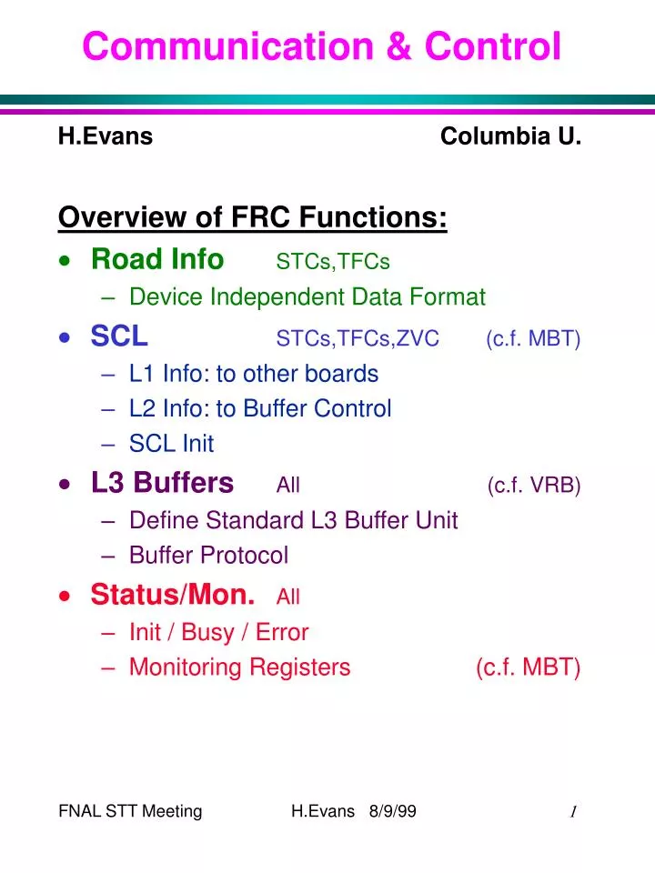
Communication & Control. H.Evans Columbia U. Overview of FRC Functions: Road Info STCs,TFCs Device Independent Data Format SCL STCs,TFCs,ZVC (c.f. MBT) L1 Info: to other boards L2 Info: to Buffer Control SCL Init L3 Buffers All (c.f. VRB) Define Standard L3 Buffer Unit Buffer Protocol

E N D
Communication & Control H.Evans Columbia U. Overview of FRC Functions: • Road InfoSTCs,TFCs • Device Independent Data Format • SCLSTCs,TFCs,ZVC(c.f. MBT) • L1 Info: to other boards • L2 Info: to Buffer Control • SCL Init • L3 BuffersAll (c.f. VRB) • Define Standard L3 Buffer Unit • Buffer Protocol • Status/Mon.All • Init / Busy / Error • Monitoring Registers (c.f. MBT)
FRC (cntrl) 1 evt Status 16 evt 16 evt G-Link Conv (SMT) SMT Fiber STC (clus) 16 evt TFC (cntrl) STC (cntrl) L3 STC Clus-Buff (z) L3 STC Clus-Buff (r-phi) Status STC (assoc) L3 STC Assoc-Buff L3 TFC Fit-Buff TFC (xmit) TFC (fit) TFC (format) Status G-Link Conv (CFT) FRC (road) L1CTT L3 FRC Road-Buff FRC (buff-ctrl) Roads + L1-SCL L1 Info Buffer Control L1 / L2 SCL Hub SCL Mezz FRC (scl) Init / Busy / Error ZVC L2CTT MBT
Road Data Format • Control Info Required with each word • Valid Data • End of Event • CLK • 3 Extra Bits for each word transferred
L1CTT Data Format See M.Martin: http://d0server1.fnal.gov/www/protocols/
L1CTT Glossary (Abridged) • Header • P/N Some Trks w/ Pos/Neg Pt • No. Ptx No. of Trks in Pt Bin x • Data • S Sign of Trk • Pt Bin Pt Bin Number (0-3) • Ext. Pt Bin-1 (1.5-3 GeV) A-Offset Bin-2 (3-5 GeV) A-Offset Bin-3 (5-10 GeV) Pt-Info Bin-4 (10- GeV) Pt-Info • H/L Trk assoc w/ Hi/Lo PS Clust • Err Transmission Errors • R PS Clust assoc in adjacent sect • PSC RA Rel. Addr of PS Clust • Rel H-Layer Fiber Number • Is Isolated Track • eI Isolated Electron • Trk Adr Address of 4.5o wedge of Trk
Serial Command Link • Steal as much as possible from MBT • see MBT TDR (ver. 5 - 5/24/99)http://macdrew.physics.umd.edu/dzero/trigger/mbt.html • L1 Accept • L1_TURN, L1_BX, L1_QUAL sent to: • STCs, TFCs, ZVC(?) as 1st element of Road Data • FRC Buffer Control to request next Buffer • L2 Accept • L1_TURN, L1_BX, L3_TRAN_NO sent to: • FRC Buffer Control to initiate Buffer Transfer
SCL (cont.) • SCL Init Sequence Command Implementation 1) FRC Rec Init from Hub mezzanine 2) FRC Send Init to all Card User pin 3) FRC INIT_ACK to Hub mezzanine 4) FRC Clear L1/L2_ERROR mezzanine 5) All Receive Init from FRC User pin 6) All Raise Local Busy VME stat reg 7) All Start Init Sequence wait until all Inputs are clear send Init Done signal 8) FRC Poll all Local Stat Regs VMEor Wait for local init_ack’s User pin 9) FRC Clear INIT_ACK mezzanine • Have to be ready for SCL Init on any 132 ns SCL word !
Buffers and Control • Steal from VRB / VRBC • see ESE-SVX-950719 (7/1/99)http://www-ese.fnal.gov/eseproj/index/svxii/svxii.htm Possible System: • FRC(buff) acts as Buffer Manager for all L3 Buffer Units in system • sends same control signals to all Units • basically: Write to Buffer i L1 AccRead from Buffer j L2 Acc • All buffer number management at FRC • control signals derived from L1/L2 SCL • decouples SCL from rest of system(aside from road data) • Use same L3 Buffer Unit on all cards • simplifies I/O • use L3 Buffer Unit on FRC ? • Control Protocol = a subset of VRBC
L3 Buffer Unit Buffer (MPM) Input FIFO Output FIFO Data Source Buffer Controller Data Message Busy/Error 16 evt Data Pointer Cmd/Addr Decode RW Route & Count Data Enable/Reset/Busy/Error Route & Count Count/Ovfl Enable/Reset/Busy/Error Data C/O Status Format/Xmit VME VBD FIFO full Addr Error Count / Status
VRB Buffer Protocol • Messages: • 12+2(?) bit Field on Ext Ctrl Port • Bits 11..8 Type 7..0 Value • Control 1..0 Valid,CLK
Buffer Protocol (cont.) • Status • in VRB: open collector TTL on J5/6 • OR of all modules
STT Control / Status • Fast Status User pins • Event-by-Event Comm. w/ Trigger • Lines to FRC are OR of all boards • SCL Init / Restart from FRC • Busy / Error / Init Ack to FRC • Each board must define • Actions for Init / Restart(w/in guidelines of SCL Init Sequence) • conditions for Busy / Error • Monitoring VME Regs • Steal from MBT (?) • Use Standard Monitoring Registers • same memory maps
FRC To Do List (from BU) • Check for Truncation Scheme Biases • Define Road Info Data Format • Decide Where Reformatting of L1CTT Info will be Done • Decide on Communications Medium • Identify SCL Info Needed • Define Data to L3 • Define Buffer Control Protocol • Define Monitoring Data / Monitoring Control • Long List of Internal FRC Decisions… • Done • First Pass • Still Pending