Download
1 / 25
250 likes | 456 Views
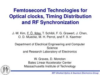
Femtosecond Optical Synchronization System for FLASH. Achievements and challenges during the first implementation phase of an engineered version in the accelerator. Matthias Felber - DESY for the LbSyn Team CLIC09 Workshop, CERN 15.10.2009.

E N D
Femtosecond Optical Synchronization System for FLASH Achievements and challenges during the first implementation phase of an engineered version in the accelerator Matthias Felber - DESY for the LbSyn Team CLIC09 Workshop, CERN 15.10.2009 V. Arsov, M. Bock, P. Gessler, K. Hacker, F. Löhl, H. Schlarb, B. Schmidt, S. Schulz, A. Winter
Agenda • Short Introduction to FLASH • Synchronization Needs and System Layout • The Basic Components of the System • Arrival Time Measurements and Feedback • RF Generation from Optical Pulse Train • Closing Remarks
FLASH – Free Electron LASer Hamburg machine layout after shutdown: March 2010 • Started as test facility for the TESLA project • Superconducting cavities at 1.3 GHz (~25 MV/m) • 3rd Harmonic Module at 3.9 GHz • Two dispersive sections for high peak currents • First user facility for VUV and soft X-ray laser pulses • Photon pulses have few 10 fs length • Pump-Probe experiments require synchronization on a 10 fs scale
Synchronization needs in an FEL facility • Goal • Measure and stabilize (feedback) timing jitter + drifts • Lock various lasers (pump-probe, diagnostic, seed, …) on a 10 fs scale • Provide extremely stable RF reference signals Master Clock Beam Diagnostics Seed laser Photo cathode laser Pump-probe laser Booster Modules Undulator • Main sources for arrival-time changes • Arrival-time of the photo cathode laser pulses • Phase of the RF gun • Amplitude and phase of the booster module(s) RF requirements for 10 fs arrival stability: Dj < 0.005° @ 1.3 GHz DA/A < 1.6*10-5
Layout of the synchronization system The reference timing information is encoded in the precise repetition rate of an optical pulse train RF Master Oscillator RF to Optical Master Laser Oscillator Laser Source locked to machine reference Distribution and active length stabilization Splitting (16 Outputs) Fiber Links (≤ 300 m) Each RF Station …….… Optical to Optical Optical to RF Optical to RF Beam Diag-nostic Optical to Optical Optical to Optical Optical to Optical Injector Laser Low Level RF Low Level RF BAM / EBPM Seed Laser Probe Laser Diagnostic Lasers (EOS, TEO) ….… GUN LINAC Undulator Pump-Probe Exp.
L2L L2L L2L EBPM EBPM TEO BAM BAM BAM DWC DWC L2RF L2RF L2L MLO MLO Schematic of the optical synchronization system at FLASH Laser building EO, HHG and ORS Photo-cathode Laser Experiment sFLASH Seed THz BC BC L2L SASE-Undulators ORS HHG RF gun BAM PP-laser BAM Energy BPM Seed EBPM Beam arrival monitor BAM MO Laser to laser synchronization Fiber link stabilization L2L Direct laser seeding Seed Distribution High precision downconverter DWC Laser to RF conversion L2RF • beam based feedback stabilization of arrival-time • high precision synchronization of lasers • synchronization of all timing critical devices (up to 14) • Point-to-point synchronization ~ 10 fs rms (< 30 fs rms to beam) • Permanent operation and long term stability / availability investigation
The synchronization lab at FLASH • Optical table (full expansion state) • two MLOs for redundancy • free-space distribution • four fiber (EDFA) distribution units • up to 14 link stabilization units (‘Fiber Links‘) • RF-lock unit for MLO • RF based link stabilization unit • Four electronic racks • four VME crates (in future mTCA) • 18 DSP controls (feedback loops) • 18 piezo drivers (± 300 V) • 20 pump laser diode drivers • 16 stepper motor drivers • > 40 temperature readouts • tons of monitor signals • ~ 300 cables to/from optical table
Master laser oscillator (MLO) • Properties • mode-locked erbium-doped fiber laser • 1550nm telecommunication wavelength • repetition rate of 216.66 MHz (1.3 GHz /6) • average power > 60 mW • pulse duration < 100 fs (FWHM) • Integr. timing jitter ~15 fs [1 kHz, 10 MHz] (limited by measurement) • amplitude noise < 2 10-4 [10 Hz, 40 MHz] • NPR type laser maybe not the best solution? Original design: J. Chen et. al., Opt. Lett. 32, 1566-1568 (2007) 1st generation MLO ‘Plan B‘ MLO 2nd generation MLO 3st generation MLO Courtesy F. Loehl, S. Schulz, A. Winter
Distribution to up to 16 outputs • Properties • baseplate made of Invar • two free space inputs, 16 collimator outputs • same pathlength for each output • 4-5 mW per output • ~ 85% incoupling efficiency at all collimators S. Schulz, FEL09, WEPC72
Fiber link stabilization 216 MHz Er-doped fiber laser J. Kim et al., Opt. Lett. 32, 1044-1046 (2007) end station Courtesy F. Loehl
Balanced optical cross-correlator (OCC) link 1 link 2 (Development in collaboration with MIT) F. Loehl, FEL08, THBAU02 time S. Schulz, FEL09, WEPC72 S. Schulz, FEL09, WEPC72
Beam arrival-time monitor (BAM) sampling times of ADCs ADC1 (108 MHz) ADC2 (108 MHz) 4.7 ns (216 MHz) M. Bock, FEL09, WEPC66 F. Loehl, PhD thesis, DESY-THESIS-09-031, 2009 Patented 2006 by DESY
Arrival time correlation between two BAMs uncorrelated jitter over 4300 shots: 8.4 fs (rms) • Arrival time difference contains: • high frequency laser noise (~3 MHz – 108 MHz) • stability of two fiber links • two BAMs • Single bunch resolution of entire measurement chain: < 6 fs (rms) F. Loehl, PhD thesis, DESY-THESIS-09-031, 2009
Beam based injector feedback • Goal: Achieve stable arrival time, energy and compression • Need: Many (different) monitor systems and complex regulation algorithms needed M. Bock, FEL09, WEPC66 Energy BPM (EBPM) Photo Cathode Laser (PCL) synchrotron light monitor SLM 1 arrival-time monitors RF Gun Booster 2 3 BPMs bunch compr. monitor Machine parameter: Monitor: Arrival-time of PCL 1st arrival time monitor Phase of RF gun difference 1st and 2nd arrival-time monitor Amplitude of booster EBPM + BPMs / difference 3rd and 2nd arrival-time monitor (/ SLM) Phase of booster module (bunch compression monitor / fiber laser + EO)
Intra bunch-train arrival time feedback 1200 shots: Intra-pulse arrival jitter reduction by a factor of 5! F. Loehl, FEL08, THBAU02
RF generation from optical pulse train here: small bandwidth PD gating lower frequencies • Direct Conversion • Drift: 10.7 fs over >15 h @ 1.3 GHz (M. Felber, PAC09, TH6REP088) • Jitter: 3.3 fs [1kHz,10MHz] @ 3 GHz (S. Hunziker, DIPAC09, TUPB43) • small and robust • 10 mW Popt sufficient • relatively cheap (<2k€) • Small output power vs. amplifier drift • Amplitude to phase conversion: 1-4 ps/mW • Temperature dependency ~350 fs/°C
RF generation from optical pulse train RF Out • Balanced optical-microwave phase detector PLL feedback loop • High power output (amplifier can be included in feedback) • Balanced scheme potential for ultra-low drift: <7 fs over 7 h (M. Felber, PAC09, TH6REP088) J. Kim et al., Nature Photonics 225: 733-736, 2008
Many more projects at LbSyn… RF-based fiber (short)link stabilization RF based measurement of link length change <5 fs over 50 h (J. Zemella, FEL09, FROA05) Two-color optical cross-correlator locking lasers of different wavelength, e.g. Ti:Sa (800 nm) (S. Schulz, PAC09, TH6REP091) Energy BPM (EBPM) use orbit dependency of pickup signal in chicane + two BAM setups (K. Hacker, FEL09, WEPC70) …
Requirements for developing a synchronization system • Infrastructure • Environment Temperature stabilization Vibration suppression EMI shielding • Typical laboratory equipment Optical spectrum analyzer Autocorrelator RF Phase- and amplitude noise analyzer Baseband analyzer Fast scopes (≥8 GHz) RF spectrum analyzer (≥26 GHz desired) Splicer + PM splicing equipment etc… • Engineering skills Optics (Free space- and fiber) Electronics (low noise analog / fast digital) FPGA programming Software (Control system integration / feedback) Mechanical (small and precise / big and robust) RF • Time, Money and Manpower
Summary & Outlook • Prototypes for all subsystems have been built and demonstrated <10 fs stability • Engineered versions of key components have been developed, some with major problems (MLO), some with good performance (Links) • At FLASH, the system is in the commissioning phase (2 MLOs, 4 Link stabilizations, 3 BAMs, and 1 EBPM in operation) • Robustness and long-term (>month) reliability tests underway • Installation of two more BAMs planned, till the end of the current shutdown (March 2010) • Still a lot of development to do…
During the past five years many fruitful collaborations contributed to the progress Thank you for your attention!
BAM Layout Courtesy M. Bock
BAM measurements – arrival time dependencies M. Bock et al., FEL09, WEPC66 Gun Amplitude Phase Acc1 Most critical at FLASH 4.8 ps/% Acc23 Acc456 no effect
BAM bunch train measurement - no arrival time feedback Shot-to-shot fluctuations and intra bunch train pattern Courtesy: F. Loehl