Download
1 / 33
360 likes | 412 Views
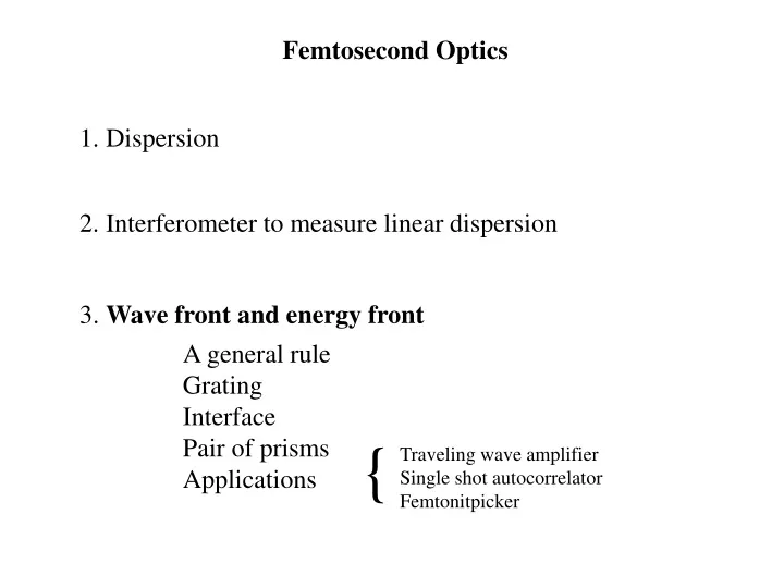
Femtosecond Optics. 1. Dispersion. 2. Interferometer to measure linear dispersion. 3. Wave front and energy front. A general rule Grating Interface Pair of prisms Applications. {. Traveling wave amplifier Single shot autocorrelator Femtonitpicker. Femtosecond Optics.

E N D
Femtosecond Optics 1. Dispersion 2. Interferometer to measure linear dispersion 3. Wave front and energy front A general rule Grating Interface Pair of prisms Applications { Traveling wave amplifier Single shot autocorrelator Femtonitpicker
Femtosecond Optics A pair of prisms: can you use it to measure the phase?
I don’t have a fs detector… There’s a hole in my bucket, dear Liza, dear Liza There’s a hole in my bucket, dear Liza, a hole Then fix it, dear Henry, dear Henry, dear Henry Then fix it, dear Henry, dear Henry, then fix it With what shall I fix it, dear Liza, dear Liza? With some straw… The straw is too long, dear Liza, dear Liza Then cut it…. In what shall I get it, dear Liza, in what? In a bucket dear Goofy, dear Henry, dear Henry
Either accurate spectral amplitude OR accurate spectral phase Cross-correlator td f(W)
How to measure ? MICHELSON AND WHITE LIGHT INTERFEROMETRY
Michelson Interferometer response If beam 2 traverses L = 2d of glass instead of air, the field E2 is modified:
Michelson Interferometer response: shift in “time origin”
Michelson Interferometer: demonstration of a delayed response
Michelson Interferometer: sample testing Without sample: With sample: sample Ratio:
Michelson Interferometer: sample testing Do we need short pulses? Can we test mirrors? We are measuring directly k(W) to all orders (except zero and one)
Michelson Interferometer: sample testing sample White light = random sequence of ultrashort pulses
Relative Delay (fs) 0 100 200 300 400 1.0 0.5 Normalized Intensity (a.u.) 0.0 -0.5 -1.0 0 30 60 90 120 m Relative Delay ( m) Interferogram for 2 mm of glass, spectrum and spectral phase. m m) Wavelength ( 1.2 1 0.8 0.6 5 1.0 Spectrum Phase 0 0.8 Polynomial Fit -5 Spectral Amplitude (a.u.) 0.6 Spectral Phase (rad) -10 0.4 -15 0.2 -20 0.0 -0.5 0.0 0.5 1.0 W (1/fs)
Mirror interferogram Reference interferogram t t Ref 1 Ref Sample mirror D D
m Wavelength ( m) 1 0.9 0.8 0.7 0.6 i. ii. 1.0 1.5 0.5 Spectral Phase (rad) 1.0 0.0 0.5 -0.4 -0.2 0.0 0.2 0.4 0.6 W (1/fs) Mirror testing: Interferogram, spectrum and spectral phase. Relative Delay (fs) 0 100 200 300 1 b. Normalized Intensity (a.u.) 0 -1 0 20 40 60 80 100 m Relative Delay ( m)
Wave front and energy front db tan g = l dl
b = q - q l dn c dl db r tan g = l i dl Tilting at an interface TAC = L sin qi/c q q Pulse n sin = sin i r TBD = L sin qrn/c TBD – TAC = -L sin qr/vg + L sin qi/c = L sin qr (n/c – 1/vg) = L sin qr q DC = L cos r A q i q i B C D’ g q r D
Consequences of an energy front tilt Focusing: expanded focal region, less intensity Cavity – pulse stretching across the transverse direction. Remedies: image reversal pairs of elements
Energy front & Phase front Fermat’s principle OPL Phase velocity Energy front (pulse propagation) Group velocity
Group delay Wave front and energy front db tan g = l db = angular dispersion g = tilt of energy front dl dl Group velocity dispersion There is also a relation between GVD and angular dispersion
S’W Q S0, SW PW rW a L r0 P0 S’0 Whether considering group delays or group velocity dispersion (GVD), we will consider sufficiently broad beams, and sufficiently short propagation distances Lp behind the element, such that diffraction effects can be neglected.
S’W Q S0, SW PW rW a L r0 P0 S’0