Download
1 / 20
200 likes | 624 Views
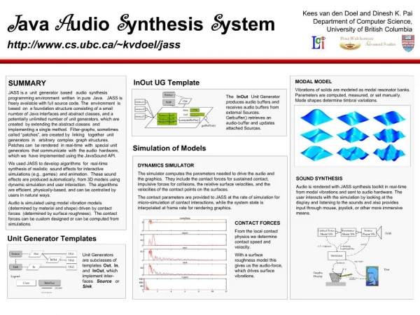
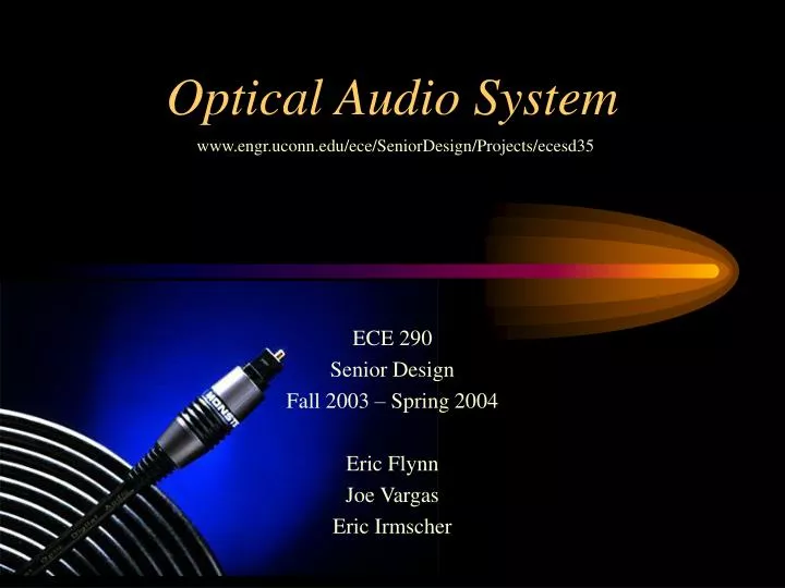
Optical Audio System www.engr.uconn.edu/ece/SeniorDesign/Projects/ecesd35 ECE 290 Senior Design Fall 2003 – Spring 2004 Eric Flynn Joe Vargas Eric Irmscher Abstract

E N D
Optical Audio System www.engr.uconn.edu/ece/SeniorDesign/Projects/ecesd35 ECE 290 Senior Design Fall 2003 – Spring 2004 Eric Flynn Joe Vargas Eric Irmscher
Abstract • Our group proposes to build a better audio system. We are going to build a higher quality, more efficient, lighter, and less interference-prone system. • We will accomplish this through: • digital transmission of the audio signal • fiber optic cables • discrete amplification
Background on Analog sound • Typical Home / Car Audio System • CD player • Amplifier • Speakers
Standard Interconnects • RCA cables • Speaker wire
Benefits of Digital Sound • Precise • Higher quality • The new medium of information transfer
Standard Benefits of Fiber Optics • Will not pick up or transmit any electrical or radio interference • Lighter than equivalent copper wires or cables • Wider bandwidth for data transmission
Design Goals • Make the system as cost effective as possible • Make the system perform better than current methods
CD Information • CD encoded with pits (0 = pit, 1 = no pit) • Read by a laser reflecting from the CD surface • Reflected laser shines on a detector when a pit is not present • Digital output of a CD player is encoded • Code is very complex (Eight - to Fourteen Modulation) • Sorting • Complex error correction scheme (can recover from approximately a 1mm damaged section.... Each bit is approximately 3 microns) • Additional bits (location on CD, etc)
Digital Audio Converter • Needed to decode the CD’s serial digital output to a two channel digital audio signal
CS8414 • It decodes the audio encryption used on Cds • It can sample up to 100kHz • Built in error checking • Small power consumption (5 volts, 10 mA) • Dedicated Audio Serial Port • Compatible with the CS4334 Digital to Analog converter
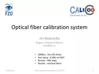
Many considerations Type of fiber Length Loss associated with each type of fiber Coupling / splicing Pulse spreading Detection Type of source Wavelength of source Fiber Optic Cable
Fibers - Basics • Types: • glass / glass • Low loss • normally used for long distance transmission (>100km) • Very expensive ($50 / 10ft) • glass / plastic • More losses than glass / glass, but less expensive ($30 / 10ft) • Normally used for medium distance transmission (~100km) • plastic / plastic • Very lossy • Inexpensive ($7 / 10ft) • Used for short distance transmission (several km at the most)
Sources and Wavelengths • Types of sources • LED • Laser diode • High power laser • Wavelengths available from 400nm to 1600nm • Visible light range from ~400nm - ~700nm • Difficult to work with invisible light • Losses associated with source wavelength
Experimentation CD player ~ $90 Speaker ~ $15 Fiber ~ $25 LED’s, emitters, detectors ~ $20 IC Chips ~ $20 Amp Kit ~ $10 Prototype Parts dependent on results from experiment Parts / Budget