Download
1 / 24
240 likes | 336 Views
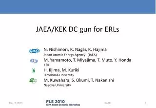
Status of 500-kV DC gun at JAEA. N. Nishimori, R. Nagai, R. Hajima Japan Atomic Energy Agency (JAEA) M. Yamamoto, T. Miyajima, Y. Honda KEK H. Iijima, M. Kuriki Hiroshima University M. Kuwahara, S. Okumi, T. Nakanishi Nagoya Univiersity. Outline.

E N D
Status of 500-kV DC gun at JAEA N. Nishimori, R. Nagai, R. Hajima Japan Atomic Energy Agency(JAEA) M. Yamamoto, T. Miyajima, Y. Honda KEK H. Iijima, M. Kuriki Hiroshima University M. Kuwahara, S. Okumi, T. Nakanishi Nagoya Univiersity
Outline • Introduction (Compact ERL, a 500 kV DC gun) • High voltage conditioning of segmented insulator with a stem electrode • 510kV for 8 hours after removing field emission site with current conditioning • High voltage conditioning with cathode electrode in place • Conditioning up to 526 kV by removing field emission site with wiping • Demonstration of 440kV for 8 hours (present status) • Plan of gas conditioning to remove field emission site • Beam generation at 300 kV • Summary and Outlook N. Nishimori, Jefferson Lab, Newport News, VA
Compact ERL (test facility) E gun (Installation by Oct. 2012 Beam generation by Mar. 2013) exp. hall Energy 35/245 MeV Current 10mA Emittance 0.1 – 1 mm・mrad LCS gamma-ray superconducting accelerator supercavity N. Nishimori, Jefferson Lab, Newport News, VA
A 500 kV photocathode DC gun at JAEA HV terminal segmented insulator stem electrode gun chamber cathode anode NEG pumps 18,000 l/s electron beam N. Nishimori, Jefferson Lab, Newport News, VA
1200 Segmented insulator 1000 Can guard ceramics against field emission generated from stem electrode. Cannot diminish field emitter itself. Reliable way to remove field emitter still needs to be developed. segmented insulator 800 6.8 MV/m 600 guard rings height (mm) 400 guard rings 8.3 MV/m field emission stem electrode 200 stem electrode 14.3 MV/m 0 stem electrode nose beam axis gun chamber -200 ceramic 0 200 400 600 N. Nishimori, Jefferson Lab, Newport News, VA radius (mm)
500kV DC gun at JAEA 550kVCockcroft Walton power supply segmented insulator SF6tank 400mm in diam. 730mm 1 m in diam. gun chamber made of titanium 3.8 m N. Nishimori, Jefferson Lab, Newport News, VA
High voltage testing with a stem electrode stem electrode 1143.5 mm 101.6 f dummy cup instead of cathode electrode N. Nishimori, Jefferson Lab, Newport News, VA
HV conditioning Why slow conditioning ? 4kV/hour 550kV • 190℃ baking for 8 hours • start conditioning at 3x10⁻⁸[Pa] • Vacuum pump: 1000L/s-TMP Because of radiation increase above 520kV R. Nagai et al., “High-voltage testing of a 500-kV dc photocathode electron gun”, RSI. 81 033304 (2010). N. Nishimori, Jefferson Lab, Newport News, VA
Conditioning with stem electrode (Oct. ’09) 600 400 HV(kV) 200 0 102 rapid increase and slow decrease every discharge 1Sv=100rem at 500kV at 500kV 1 Radiation(mSv/h) 10-2 72 76 80 84 88 time(hrs.) N. Nishimori, Jefferson Lab, Newport News, VA
Conditioning with stem electrode (Oct. ’09) 600 400 HV(kV) 200 0 102 at 500kV decrease of radiation at 550kV 1 Radiation(mSv/h) 10-2 112 116 120 124 128 time(hrs.) N. Nishimori, Jefferson Lab, Newport News, VA
Conditioning with stem electrode (Oct. ’09) 600 400 demonstration of 510 kV for eight hours HV(kV) 200 0 102 1 Radiation(mSv/h) radiation similar to B.G. level 10-2 136 140 144 148 152 time(hrs.) N. Nishimori, Jefferson Lab, Newport News, VA
Cathode electrode: POISSON calculation 6.7 MV/m cathode 100mm anode R=250 9.1 MV/m 10.3 MV/m NEG N. Nishimori, Jefferson Lab, Newport News, VA
600 Conditioning with cathode electrode (Jun. ’11) High voltage 400 HV(kV) 200 0 10-5 Vacuum 10-7 Vacuum(Pa) 10-9 1x10⁻⁹Pa 105 GMsurvey meter 103 Radiation(cpm) 10 N. Nishimori, Jefferson Lab, Newport News, VA 0 4 8 time(hrs.)
600 510kV 400 HV(kV) 200 radiation spot 0 10-5 12000 10-7 Vacuum(Pa) 8000 10-9 Radiation(cpm) 105 4000 350kV 103 0 Radiation(cpm) 0 100 200 300 400 500 HV(kV) N. Nishimori, Jefferson Lab, Newport News, VA 10 112 116 120 time(hrs.)
600 Conditioning after wiping cathode (Jun. ’11) HV 400 Go up to 445kV within 1 hour HV(kV) 200 0 10-5 Vacuum (NEG reactivated without baking) 10-7 Vacuum(Pa) 1x10⁻⁸Pa 10-9 105 GM survey meter 103 Radiation(cpm) N. Nishimori, Jefferson Lab, Newport News, VA 10 0 4 8 time(hrs.)
600 526kV 400 HV(kV) 200 radiation spot 0 10-5 100 10-7 1Sv=100rem Vacuum(Pa) 80 10-9 60 3x10⁻⁹Pa Radiation(mSv/h) 40 105 found another local radiation from survey 20 0 103 400 420 440 460 480 500 Radiation(cpm) HV(kV) N. Nishimori, Jefferson Lab, Newport News, VA 10 112 116 120 time(hrs.)
Possible local radiation sources found NEG 400L/s NEG holder Polishing powder found in holes of NEG holder parts N. Nishimori, Jefferson Lab, Newport News, VA
Status after removal of dust source (Feb. ’12) Still suffered from field emission generated from cathode electrode 12 1Sv=100rem 500 10-7 10 400 8 HV 10-8 HV(kV) 300 Radiation(mSv/h) 6 N2 equivalent pressure (Pa) pressure 200 10-9 4 100 8x10⁻¹⁰ Pa 2 10-10 0 0 2 4 6 8 0 400 (8MV/m) 460 420 440 500 (10MV/m) 480 time(hrs.) HV (kV) GM survey meter radiation spot 500 12 400 HV 8 300 0.6hours at 480kV > 8hours without discharge at 440kV 2hours at 460kV radiation(mSv/h) HV(kV) 200 4 radiation 100 0 0 0 2 0 2 4 6 8 4 6 8 0 2 4 6 8 N. Nishimori, Jefferson Lab, Newport News, VA time(hrs.) time(hrs.) time(hrs.)
Gas conditioning with segmented insulator • 10-9Pa, 10mA would produce the same amount of ion with 10-3 Pa, 10nA • Ion back-bombardment would be ~10-6 of field emission current for 10-3 Pa He gas. • No field emission from stem electrode, but some emission from backside of guard rings. • Still be careful about damage on ceramics by field emission. • Measurement of HV power supply current with high accuracy. • HVPS current with gas should be equal to that without gas. guard rings field emission stem electrode 2.6MV/m 2.6 MV/m on backside of ring 8.3 MV/m on stem electrode N. Nishimori, Jefferson Lab, Newport News, VA
I-V curve of HV power supply without gas 200 I[mA]=0.3312xHV[kV]-0.29 0.4 HVPS current 150 0.2 0.0 100 DI (mA) HV power supply current (mA) -0.2 50 deviation from fitting -0.4 0 0 100 200 300 500 400 HV (kV) N. Nishimori, Jefferson Lab, Newport News, VA
-500kV terminal Gun configuration segmented insulator preparation chamber 1.5m transfer rod HV chamber cathode loading chamber anode e beam 1m transfer rod N. Nishimori, Jefferson Lab, Newport News, VA
Downstream beam line Electron gun solenoid Beam profile monitor Bending magnet laser Beam dump Window , Laser shutter 1.2 m from anode to bending magnet 0.7 m from bending magnet to beam profile monitor N. Nishimori, Jefferson Lab, Newport News, VA
300 keV beam generation top top low-E High-E low-E High-E f2 bottom bottom diaphragm:8 diaphragm:4 • Beam profile on screen placed 1.9m downstream from anode. • 15nA@beam dump, laser power 1.4mW@532nm, QE=2.5% • 5.7mA@beam dump at maximum due to radiation from beam dump N. Nishimori, Jefferson Lab, Newport News, VA
Summary and Outlook • 500kV gun status • Scheduled to be installed by Oct. 2012 • HV test with a stem electrode: 510kV (500kV) for 8 hours without any discharge after removal of FE site by current conditioning for 50 hours • HV test with a cathode electrode: 440kV (430kV) for 8 hours without any discharge. FE site cannot be removed by current conditioning so far. • Vacuum: 8x10⁻¹⁰ [Pa] N2 equivalent in HV chamber with HV on • Beam generation at 300kV • Outlook • Repeated wiping with NEG reactivation might be a solution to 500kV • Gas conditioning with monitoring HVPS current carefully • Beam generation at > 400kV N. Nishimori, Jefferson Lab, Newport News, VA