Download
1 / 32
330 likes | 416 Views
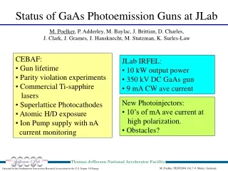
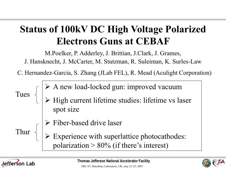
A new load-locked gun: improved vacuum High current lifetime studies: lifetime vs laser spot size Fiber-based drive laser Experience with superlattice photocathodes: polarization > 80% (if there’s interest). Tues. Thur. Status of 100kV DC High Voltage Polarized Electrons Guns at CEBAF.

E N D
A new load-locked gun: improved vacuum • High current lifetime studies: lifetime vs laser spot size • Fiber-based drive laser • Experience with superlattice photocathodes: polarization > 80% (if there’s interest) Tues Thur Status of 100kV DC High Voltage Polarized Electrons Guns at CEBAF C. Hernandez-Garcia, S. Zhang (JLab FEL), R. Mead (Aculight Corporation) M.Poelker, P. Adderley, J. Brittian, J.Clark, J. Grames, J. Hansknecht, J. McCarter, M. Stutzman, R. Suleiman, K. Surles-Law
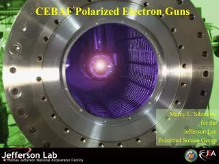
CEBAF 100kV polarized electron source • Two-Gun Photoinjector - One gun providing beam, one “hot” spare • vent/bake guns – 4 days to replace photocathode (can’t run beam from one gun while other is baking) • Activate photocathode inside gun – no HV breakdown after 7 full activations (re-bake gun after 7th full activation) • Stainless steel electrodes better than Ti-alloy, at least when cesiating inside HV chamber • 13 mm photocathode, but only use center portion, 5 mm dia. • Beam current ~ 100uA, laser 0.5mm dia., lifetime: ~ 100C, 1x10⁵ C/cm2
Ultimate Pressure = Outgassing Rate x Surface Area Pump Speed CEBAF guns test chambers New LL gun Vacuum Mystery Measured pressure always much greater than predicted* * Assume “standard” outgassing rate 10-12 and SAES-quoted NEG pump speed
Study Outgassing, NEG Pump Speed • Reasonable outgassing rates. EP and vacuum firing provides low rate with fewer bakes. • NEG pump speed very good, at least at high pressure. • Full NEG activation better than passive activation via bake • Measuring pressure below 10-11 Torr is difficult (at least for us). “Characterization of the CEBAF 100 kV DC GaAs Photoelectron Gun Vacuum System,” M.L. Stutzman, et al., Nucl. Instrum. Meth. A, 574 (2007) p. 213-220
New CEBAF load-locked gun Preparation/activation chamber Loading chamber HV chamber “suitcase”
Key Features: • Side Ceramic: nearly everything at ground potential, no moving parts at HV (thanks Bruce D.) • Suitcase for installing new photocathodes (one day to replace all pucks) • Multiple pucks, Pucks don’t roll (8 hours to heat/activate new sample) • Mask to limit active area, no more anodizing • Electropolished/vacuum fired to limit outgassing • NEG-coated
Compare NEW and OLD load locked guns (Photogun Lifetime - the best vacuum gauge?) Bulk GaAs, Green light and DC beam NEW OLD “Further Measurements of Photocathode Operational Lifetime at Beam Current > 1mA using an Improved 100 kV DC High VoltageGaAs Photogun,” J. Grames, et al., Proceedings Polarized Electron Source Workshop, SPIN06, Tokyo, Japan
Years of data from CEBAF vent/bake guns Besides vacuum, what other factors affect Photocathode Lifetime? Beam current, field emission, photocathode material, laser wavelength, laser radial position on photocathode, beam optics, what else? Install new NEGs Vacuum and Lifetime Improving?
Improve Lifetime with Larger Laser Spot? (Best Solution – Improve Vacuum, but not easy) Bigger laser spot, same # electrons, same # ions Ionized residual gas strikes photocathode Ion damage distributed over larger area
2 1500 Expectation: ≈ 18 350 Lifetime with Large/Small Laser Spots Tough to measure >1000 C lifetimes with 100-200 C runs! 5 15 “Further Measurements of Photocathode Operational Lifetime at Beam Current > 1mA using an Improved 100 kV DC High VoltageGaAs Photogun,” J. Grames, et al., Proceedings Polarized Electron Source Workshop, SPIN06, Tokyo, Japan
Conclusions • Increasing laser spot size is an easy way to improve photocathode lifetime (at expense of emittance). • Ion damage more complicated than simple model prediction (i.e. scaling not perfect): ion production not constant for two conditions, laser position/size relative to electrostatic center. • Perhaps it’s overly optimistic to extrapolate to higher current using the CEBAF experience with small laser spot (i.e., maintain demonstrated Charge Density Lifetime ~ 1x10⁵ C/cm2 at milliampere beam current). • Even extremely small beamloss is problematic. Cathode/anode optic needs to deliver all electrons to the “dump”. • Next tests: reduce cathode/anode gap to improve lifetime (next slide) • Revisit “inverted” insulator design (reduce gun surface area, eliminate external HV breakdown, implement cathode cooling? • Load locked gun drawings to be posted on the web
SS Ti Field Emission from Cesiated SS and Ti-Alloy electrodes Ti (Cesium) No cesium SS (Cesium) Without cesium, titanium and stainless steel are equivalent With cesium, stainless steel is better than titanium “Characterizing Field Emission Properties of Cesiated Cathodes of Titanium and Stainless Steel”, J. McCarter, K. Surles-Law, poster, AVS regional mtg, JLab, Apr., 2007
Recent Papers: • “A High Average Current Polarized Electron Source with Long Cathode Operational Lifetime,” C. K. Sinclair, P. A. Adderley, B. M. Dunham, J. C. Hansknecht, P. Hartmann, M. Poelker, J. S. Price, P. M. Rutt, W. J. Schneider, and M. Steigerwald, Phys. Rev. ST Accel. Beams 10, 023501 (2007). • “Generation of Electron Microbunches at Low Repetition Rates Using Beat Frequency Technique,” M. Poelker, J. Grames, J. Hansknecht, R. Kazimi, J. Musson, Phys. Rev. ST Accel. Beams 10, 053502 (2007) • “Characterization of the CEBAF 100 kV DC GaAs Photoelectron Gun Vacuum System,” M.L. Stutzman, P. Adderley, J. Brittian, J. Clark, J. Grames, J. Hansknecht, G.R. Myneni, M. Poelker, Nucl. Instrum. Meth. A, 574 (2007) p. 213-220 • “Synchronous Photoinjection Using a Frequency-Doubled Gain-Switched Fiber-Coupled Seed Laser and ErYb-Doped Fiber Amplifier,” J. Hansknecht and M. Poelker, Phys. Rev. ST Accel. Beams 9, 063501 (2006) • “The Effects of Atomic Hydrogen and Deuterium Exposure on High Polarization GaAs Photocathodes,” M. Baylac, P. Adderley, J. Brittian, J. Clark, T. Day, J. Grames, J. Hansknecht, M. Poelker, M. Stutzman, A.S. Terekhov and A.T. Wu, Phys. Rev. ST Accel. Beams 8, 123501 (2005). Recent Conferences: • “Further Measurements of Photocathode Operational Lifetime at Beam Current > 1mA using an Improved 100 kV DC High VoltageGaAs Photogun,” J. Grames, M. Poelker, P. Adderley, J. Brittian, J Clark, J. Hansknecht, E. Pozdeyev, M. Stutzman, K. Surles-Law, Proceedings Polarized Electron Source Workshop, SPIN06, Tokyo, Japan. • “Probing Hadron Structure at CEBAF Using Polarized Electron Scattering,” M. Poelker, presented at the annual meeting of the American Physical Society, Dallas, TX, April 2006. • “Operation of CEBAF photoguns at average beam current > 1 mA,” M. Poelker, J. Grames, P. Adderley, J. Brittian, J. Clark, J. Hansknecht, M. Stutzman, Polarized Sources and Targets Workshop, Nov. 14-17, 2005, Tokyo, JAPAN. • “Polarized Photoguns and Prospects for Higher Current,” M. Poelker, Workshop on Energy Recovered Linacs, Jefferson Lab, March 19-22, 2005. • “Characterizing Field Emission Properties of Cesiated Cathodes of Titanium and Stainless Steel”, J. McCarter, K. Surles-Law, poster presentation, AVS regional mtg, JLab, Apr., 2007
Harmonic-modelocked Ti-Sapphire CEBAF Lasers Diode-seed + diode-amp 1996 M. Poelker, Appl. Phys. Lett. 67, 2762 (1995). 2000 C. Hovater and M. Poelker, Nucl. Instrum. Meth. A 418, 280 (1998);
Commercial Ti-Sapphire • 1st commerical laser w/ 499 MHz rep rate • Higher power compared to diode lasers • Wavelength tunable for highest polarization • Feedback electronics to lock optical pulse train to accelerator RF
System Availability FY05Q4 – FY06Q3 Realign Ti-Sapphire lasers each week
New Fiber-Based Drive Laser J. Hansknecht and M. Poelker, Phys. Rev. ST Accel. Beams 9, 063501 (2006) • CEBAF’s last laser! • Gain-switching better than modelocking; no phase lock problems • Very high power • Telecom industry spurs growth, ensures availability • Useful because of superlattice photocathode (requires 780nm)
~ 30 ps Fiber-based Drive Laser e-bunch (superlattice) autocorrelator trace
Pulsewidth Variablity • Diodes from different vendors produce different pulsewidths when gain-switched: depends on cavity length (and photon lifetime) e.g., Anritsu laser: 30 ps, Alcatel laser: 55 ps • According to Aculight, longer pulses (~ 70ps) can be obtained using DC diode seed laser and in-line fiber modulator. E.g., EOSpace AZ-0K5-20-PFA-PFAP-R3 • Shorter pulses? Gain-switching tricks? Modelocked diode/fiber seed lasers? • Avenue for laser pulse-shaping?
B C A Other Benefits of Fiber Drive Laser • Replace lossy free-space optics components with telecom stuff? • Green version for FELs, ERLs, electron cooling, positron sources, compton polarimeter. JLab building 2W green-light fiber system now. • “Beat Frequency Technique” to create Low Rep Rate Beam for Particle Identification at Halls: Beat Frequency Technique; Laser at 468 MHz, 31 MHz beam to Hall Normal Ops; Three beams at 499 MHz Every 15th pulse delivered to hall: 31 MHz beam M. Poelker, et al., Phys. Rev. ST Accel. Beams 10, 053502 (2007)
JLab ADL for 100mA ERL Injector All solid, DPSS MOPA system high power, high rep. rate, short pulse laser Shukui Zhang, JLab FEL Oscillator: 1.064um 25ps/1W 75&750MHz Pre-amplifier plus 3 Power-amplifiers > 50W@1064nm > 25W@532nm(75MHz) > 13W@532nm(750MHz) M² <1.3 Pulse width: 25ps Beam size: 2mm Power stability: 0.5% Pointing stability: 20urad RMS timing jitter: 300fs Picture here *Reference: S.Zhang et al., Proced. 27th International FEL conference, JACowW / eCon C0508213, pp 351-354
Overall Schematic Black: Basic structure Blue: With contrl/Diag. C: camera AC: Autocorrelator PM: Power meter PD: Photo-diode EO: electroptic modulator MS: Mechanical shutter WP:Wave-plate BBP: B-angle Pola. Prism BE: Beam expander IS: Iris A: Aperture
Strained GaAs: GaAs on GaAsP Superlattice GaAs: Layers of GaAs on GaAsP Bulk GaAs 100 nm 100 nm 14 pairs “conventional” material QE ~ 0.15% Pol ~ 75% @ 850 nm No strain relaxation QE ~ 0.8% Pol ~ 85% @ 780 nm High QE ~ 10% Pol ~ 35% Both are results of successful SBIR Programs Photocathode Material
Superlattice Photocathodes • Success required ~ 1 year of effort • Cannot be hydrogen cleaned (M. Baylac) • Arsenic capped (worked with vendor SVT) • No solvents during preparation! (M. Stutzman) M. Baylac et al., “Effects of atomic hydrogen and deuterium exposure on high polarization GaAs photocathodes” PRST-AB 8, 123501 (2005) Anodized edge: a critical step No depolarization over time! Polarization Oct 13 QE dropped by factor of 2 Nov 9
Useful Photogun Metrics What metrics best aid discussion within/among groups? Can we adopt standardized metrics? • Operating current (obvious) • Charge extracted per hour, day • QE of typical photocathodes (e.g., 10% bulk Gas, 1% for superlattice GaAs, 10% for CsK2Sb, etc.,) • Required laser power. Assume we need headroom to operate for “One Charge Lifetime”. In other words, multiply by 3. • Maximum Available laser power. Hopefully lots more than you need. • Then, you need to build the gun and measure Charge Lifetime. Hopefully, numbers (QE, max available laser power, charge lifetime) are large enough to operate without interruption for desired length of time.
Lifetime Metric • Everyone wants a gun that can operate uninterrupted for many days/weeks. • The “Clock Hours Lifetime” is a meaningful metric within a particular group. How often is maintenance required? • But Clock Hours Lifetime not necessarily a useful metric between groups (because not all machines operate around the clock) • On the other hand, desired Clock Hours Lifetime is an important number when defining gun requirements for a new machine. i.e., you would like to operate for XX hours before intervening to repair/replace photocathode.
QE = Charge lifetime ln initial Charge extracted QE final Reminder… 124 * Current (mA) QE = Laser power (W) * Wavelength (nm)
Example: Requirements for 100 mA ERL • 100mA operation, 360 C/hr, 8640 C/day. • Bulk GaAs at 532 nm, 10% initial QE • Initial laser power = 2.3W, “Final” laser power = 6.3W after “one charge lifetime” • If your gun provides 1000C charge lifetime, and you have maximum laser power of 6.3W, you can run for 2.8 hours. • If on the other hand, you have 100W laser power, you can operate at 100mA until QE falls to 0.23% and deliver 3772C over 10.5 hours. • For 100W green laser and 10,000C charge lifetime, you can operate at 100mA and deliver 37,722C until QE falls to 0.23%, providing 4.4 days of uninterrupted operation.
But QE is not constant… …when surface is damaged or dirty Surface Charge Limit – not just a problem for high bunch charge, pulsed-machines