Download
1 / 36
360 likes | 492 Views
TCM-8 meeting, 2010, April 14 ENEA Frascati, Italy. JT-60SA Plasma Regimes and Research Plan. Y. Kamada JAEA. The JT-60SA Project. The JT-60SA project is conducted under the BA Satellite Tokamak Programme by Europe and Japan, and the Japanese National Programme.

E N D
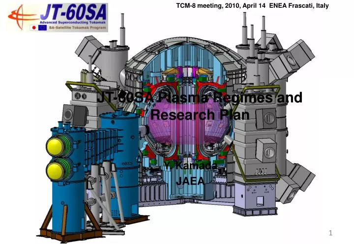
TCM-8 meeting, 2010, April 14 ENEA Frascati, Italy JT-60SA Plasma Regimes and Research Plan Y. Kamada JAEA
The JT-60SA Project The JT-60SA project is conducted under the BA Satellite Tokamak Programme by Europe and Japan, and the Japanese National Programme. The project mission is to contribute to early realization of fusion energy by supporting exploitation of ITER and by complementing ITER with resolving key physics and engineering issues for DEMO reactors. JT-60SA and ITER should be operated as a ‘set’, in order to realize the Fusion Energy for both * science and technology * scientists
6 5 4 3 2 1 0 JT-60SA Plasma Regimes JT-60SA is a fully superconducting tokamak capable of confining break-even equivalent class high-temperature deuterium plasmas(Ip-max=5.5 MA) lasting for a duration (typically 100s) longer than the timescales characterizing the key plasma processes, such as current diffusion and particle recycling. JT-60SA should pursue full non-inductive steady-state operations with high bN (> no-wall ideal MHD stability limits). DEMO reactors JT-60SA Target bN ITER Steady-state JT-60U Existing Tokamaks ITER Inductive 0 20 40 60 80 100 400 3000 Sustainment Time (s)
EU & JA Share Procurements Naka site Design of the key components has been almost completed. The JT-60SA project has been entered its manufacturing stage. Power Supplies Compressor Building Magnet Interface Water Cooling System CS, EF coils TF coils&Testing 700t 150t NBI Cryogenic System ECRF Cryostat Laser scattering 16m Diagnostics Rad. safety Vacuum Vessel Cont/data In-vessel Components Body: 350t Assembly Base: 260t Remote Handling Disassembly
JT-60SA: Highly Shaped Large Superconducting Tokamak • A wide range of plasma equilibrium covering a high plasma shaping factor of S=q95Ip/(aBt) ~7 and a low aspect ratio of A~2.5 with a sufficient inductive plasma current flattop and additional heating up to 41 MW during 100 s. The plasma size is ~ 0.5 x ITER = between ITER and other superconducting tokamaks. An integrated knowledge of superconducting tokamaks SST-1, EAST, KSTAR, TORE-SUPRA, JT-60SA and ITER will establish a reliable nuclear fusion science and technology towards DEMO.
Typical Plasma Parameters Ip=5.5MA, Double Null Ip=4.6MA ITER-shape
JT-60SA device has been designed in order to satisfy the central research needs for ITER and DEMO JT-60SA device Fully Superconducting Large Tokamak Highly Shaped Plasma Configuration Strong Heating and Current Drive Power with Variety & Long Pulse Large Capability of Stability Control Large Capability of Divertor Power Handling and Particle Control Variety of High Resolution Diagnostics
41MWx100s High Power Heating with Variety variety of heating/current-drive/ momentum-input combinations NB: 34MWx100s Positive-ion-source NB 85keV 12units x 2MW=24MW COx2u, 4MW CTRx2u, 4MW Perpx8u, 16MW Negative-ion-source NB 500keV, 10MW Off-axis for NBCD NB ECRF ECRF: 110GHz, 7MW x 100s 9 Gyrotrons, 4 Launchers with movable mirror >5kHz modulation
Research phases and status of key components JT-60SA operation starts earlier than ITER’s hydrogen operation by ~5 years. The tight schedule of ITER up to DT1 requires sufficient explorations of the key physics and operational techniques in satellite devices. => Experiences and achievements in JT-60SA are indispensable for smooth and reliable progress of ITER.
Divertor & Wall Material Research for DEMO Extended Research Phase: Installation of the metallic divertor targets and first wall together with an advanced shape divertor will be conducted based on progress of the research in the world tokamaks including ITER. Replaceable Divertor Cassette Integrated Research Phase: The material of the divertor target and the first wall is now considered to be carbon before achievement of the JT-60SA’s main mission of the high-b steady-state. However, possibility of replacement to metallic materials will be discussed based on the results in JET, ASDEX-U, FTU.
ITER & DEMO-relevant non-dimensional regime JT-60SA allows explorations in the ITER- and DEMO-relevant plasma regimes in terms of non-dimensional plasma parameters at high plasma densities in the range of 1×10²⁰/m3.
ITER & DEMO-relevant heating condition / scan JT-60SA allows dominant electron heating, scan of power ratio to electron high power heating with low central fueling high power heating with low external torque input ( incl. scan of rotation) ECH (110GHz, 7MW) N-NB (500keV, 10MW) => Electron Heating dominant Low Particle input Low Torque input P-NB (85keV, 24 MW) => Ion Heating dominant Perp-NB & balanced CO/CTR-NB => low torque input ( torque input scan)
Study on highly self-regulating plasmas for DEMO High beta & high bootstrap fraction => strong linkages among j(r), p(r), Vt(r) + Global linkage / Global structure including core & pedestal + Linkage among transport coefficients & roles of MHD activities => JT-60SA allows understanding & control of this plasma system at ITER- & DEMO-relevant non-dimensional parameters (r*,n*, bN, bp, q95…) JT-60SA plasma actuator system allows separated controls for heating, current drive, rotation drive & fueling.
Demonstration & Study of High Beta (>non-wall limit) for DEMO JT-60SA allows exploitations of high beta regimes with the high shape factor S up to 7, the stabilizing shell, the RWM control coils, the error field correction coils, and the high power heating & CD & momentum-input. For DEMO, minimum rotation for RWM stabilization has to be studied => w/o control coils. Identification of the disruption limits at high bN. Stabilizing plate bNno-wall = 3.12 RWM control coils bNideal-wall =4.40 bNcritical = 4.32
JT-60SA supports ITER’s main mission & commissioning with high Ip, high power, high density plasmas JT-60SA has sufficient power for L-H transition & H-mode confinement studies at Ip=5.5MA & ne=1020m-3. JT-60SA provides data & techniques for • * H-mode operations towards Q=10 • L-H transition • Pedestal Structure • H-mode confinement ( incl. compatibility with • radiative divertor, RMP, etc.) • Disruption behavior, • and disruption prediction & mitigation using the same • techniques planed in ITER. • Operation scenario optimization with superconducting • PF coils. • Divertor heat load mitigation ( incl. ELMs) and particle • controllability • with 10MW high energy (500keV) N-NB; • NB Current Drive studies (incl. off-axis NBCD), • AE mode stability & effects on fast-ion transport, • Interactions between high energy ions and MHD instabilities
ELM mitigation for ITER and DEMO JT-60SA’s high Ip high power H-mode plasmas allow type I ELM studies at sufficiently low edge collisionality. • ELM mitigation by RMP & pellet inj. for ITER. 2) JT-60SA’s high triangularity plasmas allow small ELM regimes ( i.e. grassy ELM) for DEMO. (DEMO-equivalent shape ) => ELM mitigation without RMP. Error field correction / generation coils are used for RMP JT-60SA JT-60SA ELM energy loss fraction collisionality
High Energy Particle Studies for ITER & DEMO JT-60SA allows exploitations of NB Current Drive studies (incl. off-axis NBCD), AE mode stability & effects on fast-ion transport, Interactions between high energy ions and MHD instabilities with 10MW high energy (500keV) N-NB.
Divertor Power Handling for ITER & DEMO CFC monoblock divertor target allows 15MW/m2. Test at JEBIS at 15MW/m2 for 12 full-size mock-ups of monoblock target with 10 CFC blacks. About half of mock-ups satisfied the requirements Qualified targets survived 2000 heat cycles (30x30x30mm) The ITER-like W-shaped divertor with a V-corner enhances divertor radiation. 10.4 MW/m2 == SONIC code simulation == • The peak heat flux can be suppressed within the mono block capability (15 MW/m2) by gas puffing for 41 MW injection. (ne,ave~1x10²⁰ m-3 at fGW=0.8). Heat flux density on the LFS target • At lower ne compatible with lower Ip plasmas, qpeak = 8.6 MW/m2 is obtained with impurity seeding. Radiation map
Fuel & Impurity Particle Control for ITER & DEMO JT-60SA demonstrates particle controls under saturated wall condition by utilizing variety of the fuelling and pumping systems (gas-puffing from man and divertor, pellet injection, divrtor pumping). Compatibility of the radiative divertor with impurity seeding and sufficiently high fuel purity in the core plasma should be demonstrated. The key point is to clarify whether a wide range of the divertor plasma controllability can be realized independently of the main plasma operation condition. Divertor pumping with cryopumps allows Pumping speed of 0 -100m3/s by 8 steps. • Divertor condition can be controlled from attached to detached conditions with constant main plasma density.
High Integrated Performance for DEMO ‘Simultaneous & steady-state sustainment of the key performances required for DEMO’ has never been achieved => the goal of JT-60SA. Example of JT-60SA at Ip=2.3MA.
Integrated Control Scenario Development Understanding & Control of the highly self-regulating combined plasma system for DEMO High-beta, high-bootstrap fraction plasma => a highly self regulating non-linear system governed by strong linkages among j(r), p(r) and Vt(r) in core & pedestal. Strong spatial linkage : Core – Pedestal – SOL – Divertor plasmas Study controllability & Plasma response Determine the minimum suitable set of actuators & logic. + control margin against operation boundaries (In particular disruption limits)
Summary The project mission of JT-60SA is to contribute to early realization of fusion energy by supporting exploitation of ITER and by complementing ITER for DEMO. JT-60SA device has been designed in order to satisfy all of the central research needs for ITER and DEMO, in particular, ‘Simultaneous & steady-state sustainment of the key performances required for DEMO’ & ‘Integrated Control Scenario Development ‘.
JT-60SA is indispensable for ITER & DEMO JT-60SA operation starts earlier than ITER’s hydrogen operation by ~5 years. The tight schedule of ITER up to DT1 requires sufficient explorations of the key physics and operational techniques in satellite devices. => Experiences and achievements in JT-60SA are indispensable for smooth and reliable progress of ITER. For DEMO, an integration of achievements in JT-60SA high-b steady-state plasmas and ITER burning plasmas is required to make DEMO designs more realistic and attractive. For early realization of DEMO, such integrated exploitation of JT-60SA and ITER is necessary.