Download
1 / 28
280 likes | 392 Views
C. Baltay Aygust 8,2011. Chronopixels. Monolithic CMOS Pixel Detectors for ILC Vertex Detection. C. Baltay, W. Emmet, D. Rabinowitz Yale University Jim Brau, N. Sinev, D. Strom University of Oregon. SiD Vertex Detector Layout. 5 barrel layers 4 end disks. 5 Tesla. R

E N D
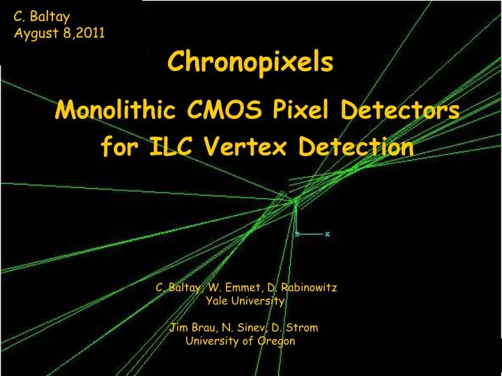
C. Baltay Aygust 8,2011 Chronopixels Monolithic CMOS Pixel Detectorsfor ILC Vertex Detection C. Baltay, W. Emmet, D. Rabinowitz Yale University Jim Brau, N. Sinev, D. Strom University of Oregon
SiD Vertex Detector Layout 5 barrel layers 4 end disks 5 Tesla R [cm] SiD00
SiD Vertex Detector • BARREL • 100 sensors • 1750 cm2 • FORWARD • 288 sensors • 2100 cm2 Consider Typical Chip of 12.5cmx2.2cm
Time Structure for the ILC Design Assume this design for the ILC Background Calculation: At 1.5 cm from Interaction Point with 3 Tesla field expect 0.03 hits /mm2/bunch crossing Will use this number for the entire detector
Monolithic CMOS Pixel Detectors What are they? New CMOS technology makes pixels as small as 10 µ x 10 µ possible Each pixel has its own intelligence (electronics) under the pixel Unlike CCD’s, all pixels are NOT read out in a raster scan Reads out x,y coordinates only of pixels with hit (i.e., exceeding an adjustable threshold) at 50 MHz Monolithic design – photosensitive detector pixel array and read out electronics for each pixel on the same piece of silicon – can be quite thin (less then 50 µ)
Conceptual Design • During the past years, working with SARNOFF, we developed a conceptual design that: • we believe will work for an ILC Vertex Detector • that SARNOFF believes they can build. • Plan to integrate over pulse train and readout during 200 msec between trains to avoid EMI (Electromagnetic Interference) during train. • Occupancy would be too high • BUT – for each hit, readout x,y, AND time of hit (time to better than 300 nsec precision effectively tagging each hit with its bunch crossing number) • Therefore the name Chronopixel • In analyzing Vertex detector data look only at hits which occurred in the same single bunch crossing • Occupancy ~ 10-6 at 0.03 hits/mm2!!
Current Design • Monolithic CMOS Process (0.045 micron technology) • Single Layer of Pixels,in the range of 10umx10um to 15um to 15um • Detect Hits above adjustable Treshhold • Store time of Hit, up to 4 hits/pixel • Integrate over Bunch Train, Readout during 200 msec between trains • Digital Readout(no Analog)
Simplified Chronopixel Schematic Essential features: Calibrator, special reset circuit Nick Sinev LCWS10 Vertex session March 28, 2010
Signal to Noise Considerations • Would like 99% efficiency even for particles whose charge is shared evenly between two pixels. • Would like threshold to be at 5 sigma of the noise to keep fake hits to below 1/3 of the real hits i.e. <0.01hits/mm2 or 10-6/pixel Epilayer (μ) electrons at 99% threshold acceptable noise 4 40 20 4 7 125 63 13 10 250 125 25 15 400 200 40 20 550 275 55
Readout Procedure and Speed • Expected hit rates: • Consider chips 22 mm x 125 mm = 2750 mm2 • Total no. of 10 µ x 10 µ pixels = 27.5 x 106 pixels/chip • Total hits .03 x 2820 bunches x 2750mm2 = 2 x 10⁵ hits/chip • Number of bits to read out one hit pixel X info ( up to 2200) – 12 bits + parity = 13 bits Y info (up to 12500) – 14 bits + parity = 15 bits Time (up to 3000) -12 bits +2 parity = 14 bits 42 bits total • 2 x 10⁵ hits/chip x 42 bits/hit/50 MHertz = 168 msec. • This should work,but not much safety margin in case the background is much higher then anticipated. • Preferred Readout scheme- • Divide device into 40 segments,read these out in parallel into a FIFO buffer at 50MHertz (~4msec) • Read out FIFO buffer at 1/2 Ghertz (~16 msec) • This has a factor of ~10 safety margin (we have 200 msec) • The 42 bits/hit and the readout time can be further reduced by a more clever readout scheme.
Charge Spreading • It is important to keep charge spreading to much smaller than the pixel size so that we can give up on the analog information. • How small can we keep the charge spreading • Thickness of expitaxial layer – 15 µ • Deplete expitaxial layer – need high resistivity, ~ 10 Kohm cm -- Can keep charge spreading to a few microns 3D Simulations under way to study these effects (Nick Sinev)
Power Reduction Method * Activate the Detector and the Comparator during the Bunch Train (~2msec) and deactivate during the Readout time(~200 msec) * Power reduction Ratio of ~ 1/100 * 0.37 Watts per 2cmx12.5cm chip( 15mWatts/sqcm) * We expect that this can be further reduced
Other Considerations • Dark Current • Will reset array after each bunch crossing so dark current should not be a problem during 337 nanosec • Operating Temperature • Sarnoff expects modest cooling (~0oC adequate) • Device Thickness • Thinning to ~ 50 μ looks feasible
The First Prototype • The ultimate design calls for • 45 nm Process Technology • 10 to 15 micron pixels • 15 micron thick epilayer • High resistivity Silicon • What was easily available for prototype 1 • 180 nm Process Technology • Can do 50 micron pixels • Readily available Si with routine TSMC fabruns has 7 micron epilayer and low resistivity
The First Prototype • In order to get first prototype quickly and for a cost we can afford we opted for the TSMC process with the readily available Si with 7 micron epilayer and low resistivity • The main purpose of this first prototype is to test the electronics performance of the chronopixel design such as noise performance,comparator accuracy and stability,scan speed and power dissipation • Fab started,expect batch of 40(minimum order) devices in February of 2008
Completed Layout • Completed Layout of Sarnoff fits 563 transistors into 50 mm x 50 mm pixels for 180 nm technology • Detector sensitivity 10 mV/e (eq. to 16 fF) • Detector noise 25 electrons • Comparator accuracy 0.2 mV rms (cal in each pixel) • Memory/pixel 2 x 14 bits each • Ready for 5mmx5mm array submission • Designed for scalability eg. no capacitors in signal path
The First Prototype • Prototype 1 Fab finished • Fabricated 40 5x5 mm chips, • 50μ x 50μ pixels • TSMC 0.18 μ technology • Epi-layer 7 μ • Low resistivity (~10 ohm*cm) silicon • Test electronics completed and debugged • Designed and fabbed at SLAC • Chronopixel chip tests completed Nick Sinev LCWS10 Vertex session March 28, 2010
Results of tests of First Prototype • Tests show that the general concept is working. • Mistake was made in the power distribution net on the chip, which led to only small portion of it being operational. • Calibration circuit works as expected in test pixels • Noise figure with “soft reset” is within specifications ( Measure noise of24 e, specification is 25 e). • Sensitivity measured to be 35.7μV/e, exceeding design spec of 10μV/e. • Comparator accuracy 3 times worse then spec, need to improve this in prototype 2. • Sensors leakage currents (1.8·10-8A/cm2) is not a problem. • Readout time satisfactory
Plans for Prototype 2 • Design of the second prototype underway • Planning on TSMC 65 nanometer process • Designing for 18 micron x 18 micron pixels • Correct mistakes of first prototype • Changing to NMOS process for improved charge collection efficiency • Expect TSMC fab run late this calendar year
Signal to Noise • Signal due to particle crossing Silicon has a broad distribution • Peak or mean signal is not the relevant consideration • Question to ask is at what signal level (i.e. at what threshold) do we detect >99% of the particles • Charge may be shared between two pixels