Download
1 / 27
270 likes | 445 Views
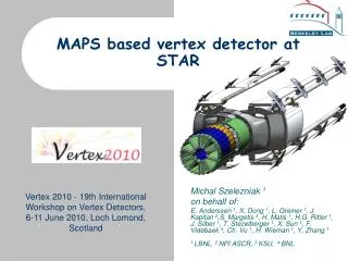
CMOS pixel vertex detector at STAR. Michal Szelezniak on behalf of: LBNL : E. Anderssen, L. Greiner, H. Matis, T. Stezelberger, X. Sun, Ch. Vu, H. Wieman

E N D
CMOS pixel vertex detector at STAR Michal Szelezniak on behalf of: LBNL: E. Anderssen, L. Greiner, H. Matis, T. Stezelberger, X. Sun, Ch. Vu, H. Wieman IPHC: A. Besson, A. Brogna, G. Claus, C. Colledani, A. Dorokhov, G. Doziere, W. Dulinski, M.Goffe, D. Grandjean, A. Himmi, Ch. Hu, K. Jaaskelainen, M. Koziel, F. Morel, A.Shabetai, I.Valin, M. Winter
Outline • PIXEL detector as a part of the Heavy Flavor Tracker • PIXEL detector characteristics • MAPS as the sensor technology for PIXEL • Development of MAPS for PIXEL • Development of the readout electronics for PIXEL • Summary and future work
HFT and PIXEL detector Heavy Flavor Tracker (HFT) will extend the physics reach of the STAR experiment for precision measurement of the yields and spectra of particles containing heavy quarks • TPC points at the SSD ~ 1 mm • SSD points at the IST ~ 300 µm • IST points at the PIXEL ~ 250 µm • PIXEL points at the vertex <30 µm The key requirement for the physics program is to: Resolve displaced vertices (>60 µm) Heavy Flavor Tracker (HFT) PIXEL at 2.5 and 8 cm IST at 14 cm SSD at 23 cm
PIXEL detector characteristics • Two layers at 2.5 & 8 cm radii • Sensor spatial resolution < 10 μm • Coverage 2πin φand |η|<1 • Over 400 M pixels • 0.28 % radiation length/layer (VXD3 0.4%, ALICE pixel detector ~1%) • Thinned silicon sensors (50 μm thickness) • Air cooled • Power dissipation ~100 mW/cm2 • Quick extraction and detector replacement • Stability and insertion reproducibility within a 30 μm window • Integration time <200 μs (L=8×1027) • Radiation environment at the level of up to 300 krad/year and 10×1012/cm2 Neq /year Very challenging mechanical and sensor design
PIXEL detector design Cabling and cooling infrastructure New beryllium beam pipe (0.5 mm thickness, 2 cm radius) Mechanical support with kinematic mounts 2 layers Detector extraction at one end of the cone Ladder with 10 MAPS sensors (~ 2×2 cm each)
Monolithic Active Pixel Sensors MAPS pixel cross-section (not to scale) Properties: • Standard commercial CMOS technology • Sensor and signal processing are integrated in the same silicon wafer • Signal is created in the low-doped epitaxial layer (typically ~10-15 μm) → MIP signal is limited to <1000 electrons • Charge collection is mainly through thermal diffusion (~100 ns), reflective boundaries at p-well and substrate → cluster size is about ~10 pixels (20-30 μm pitch) • 100% fill-factor • Only NMOS transistors inside the pixels MAPS technology is an attractive choice for the PIXEL detector
Sensor prototypes for Pixel Based on tests of several different prototypes S/N>12 allows detection efficiency >99.6% • MimoSTAR 2 prototype in AMS 0.35 technology • 128 × 128 pixel (30 µm pitch) • 4 ms integration time • Analog readout • Radiation tolerant diode design (elimination of the thick oxide from the vicinity of the charge collecting diode) • JTAG controlled configuration MAPS show promising performance for the PIXEL detector
MimoSTAR3 – large area prototype Dead pixels in the center of the sensors • Extension of MimoSTAR 2 • AMS 0.35 • Analog readout • Pixel array 320 × 640 • 30 µm pixel pitch • 2 parallel outputs • 10 parallel sub-arrays • Integration time 2 ms Low fabrication yield in the first run Mean pixel values Two fix the problem 2 masks were modified to reduce: • Surface of active area • Density of metal 1 layer Edge Center Yield improved from <20% for old layout to >80% for the new layout No contact
Transition from analog to binary readout Analog readout – simpler architecture but ultimately slower readout Digital readout – offers increased speed but requires on-chip discriminators or ADCs • Typical sensor readout • Raster scan • Charge integration time = array readout time • Multiplexing sub-arrays decreases integration time • Column parallel readout architecture • All columns are readout in parallel and then multiplexed to one output • Charge integration time = column readout time On-chip data sparsification overcomes limitation in the readout speed
Sensor with binary readout Y. Degerli et al, IEEE TNS, vol 53, no 6, 2006, pp 3949 - 3955 Y. Degerli et al, IEEE TNS, vol 52, no 6, 2005, pp 3186 - 3193 Mimosa 8/16 pixel and column level circuitry Mimosa 8/16 (TSMC 0.25/AMS 0.35) • 128 × 32 pixels with 25 μm pitch • In-pixel CDS • Column level offset-compensated discriminators Prototypes Mimosa 8 and Mimosa 16 developed by IPHC and DAPNIA feature binary readout – a major step towards on-chip data sparsificaiton
Mimosa 16 performance Meets PIXEL requirements Phase-1 prototype for PIXEL • extension of Mimosa 16 to full reticle • Integration time of 640 µs • Continuous binary readout of all pixels • This chip is ready for production
Final sensor for the PIXEL detector • Phase-1 combined with on-chip zero suppression • On-chip zero suppression has been successfully implemented and tested at IPHC as a small size prototype ~ 3 mm • The prototype zero-suppression circuitry works up to 115 MHz • Radiation hardness tests are in preparation
ADC CDS Data sparsification readout to DAQ Pixel Sensors CDS Disc. PIXEL detector readout Coupled nature of readout and sensor development Complementary detector readout digital signals analog signals digital analog MimoSTAR sensors 4 ms integration time Phase-1 sensors 640 μs integration time Ultimate sensors < 200 μs integration time First prototypes in hand and tested 2010 (planned) Install 3-module engineering prototype (based on Phase1) 2011 (planned) Install final detector
Telescope and readout prototype in STAR Leo Greiner presented MimoSTAR2-based telescope prototype with prototype PIXEL readout system at Vertex 2007
Readout system - physical layout 10 parallel independent readout modules (4 ladders per module)
LVDS data transfer • The final detector system is expected to have LVDS data transfers at the maximum rate of 160 MHz Ladder mock-up with 1-to-4 LVDS fanout buffers 42 AWG wires Mass termination board + LU monitoring 24 AWG wires Buffered path 160 MHz 2.3 m cables Bit Error Rate < 10-14 Virtex-5 based RDO system with RORC link to PC Virtex-5 individual IODELAY was adjusted for each channel
Summary • Full reticle 2 × 2 cm Phase-1 should be available at the end of this year • detector engineering prototype (3/10 of the complete detector) will be constructed and should allow to perform physics measurements in 2010 • The readout concept has been validated with LVDS readout test and the full readout system production prototypes are being developed • New prototypes with on-chip discriminators are capable of the required S/N ratio for >99% detection efficiency but with a limited safety margin • Limited S/N makes the sensors susceptible to radiation damage • ionizing damage increase of leakage current and noise • non-ionizing damage charge losses in bulk • Resistance to radiation damage level that can be expected in the STAR environment with the final luminosity (8×1027 /cm2/s ) is being carefully studied.
On-going and future development • Possible significant improvement of radiation tolerance can be achieved with different fabrication technologies: • Graded substrate and deep p-implants • simulations indicate reduction of charge collection time from ~100 ns to ~20 ns • First prototypes are under test • High resistivity substrate • On-going investigation of technology with pin diodes • 1 k cm would allow ~10 µm depletion of epi layer (~14 µm total thickness) with 3-5 V • A prototype sensor has been submitted for production • Results should be available next year – in time for Vertex 2009
Heavy Flavor Tracker @ STAR • Extend the physics reach of the STAR experiment for precision measurement of the yields and spectra of particles containing heavy quarks: • Study charm and beauty energy losses to test pQCD in a hot and dense medium at RHIC • Charm flow to test thermalization at RHIC • Direct reconstruction of charm • Detect charm decays with small cτ, including D0 and Λc+ • Method: Resolve displaced vertices (>60 µm) ~100 µm
10.7 mm 19.3 mm MimoSTAR3 – large area prototype • Extension of MimoSTAR 2 • AMS 0.35 • Analog readout • Pixel array 320 × 640 • 2 parallel outputs • 10 parallel sub-arrays • Integration time 2 ms Low fabrication yield in the first run Dead pixels in the center of the sensors Mean pixel values
MimoSTAR3 – low yield investigation Metal 4 Metal 3 Metal 2 Metal 1 • No problems were observed on the small surface area prototypes on the same wafer • Vias are the same size • Different distance between metal layers Corner Center No contact
MimoSTAR3 - layout modification 2 masks were modified to reduce: • Surface of active area • Density of metal 1 layer (GND) old layout vs. new layout Yield improved from <20% for old layout to >80% for the new layout
Readout path 10 parallel independent readout modules
Fast, column-parallel architecture Developed in IPHC - DAPNIAcollaboration A1 Voff1 A2, Voff2 Vin1,2 VC VS_READ VREAD,CALIB CDS at column level (reduces Fixed Pattern Noise below temporal noise)
LVDS data transfer – test results • Buffered path 160 MHz 1.0 m cables • Un-buffered path 160 MHz 1.0 m cables Bit Error Rate < 10-14 • Buffered path 160 MHz 2.3 m cables