Download
1 / 37
370 likes | 453 Views
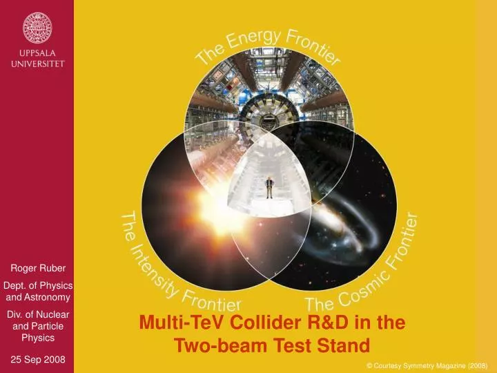
Multi-TeV Collider R&D in the Two-beam Test Stand. © Courtesy Symmetry Magazine (2008). Outline. This lecture technologies for a future linear collider related R&D in the Two-beam Test Stand Sections introduction accelerating gradient RF power production

E N D
Multi-TeV Collider R&D in theTwo-beam Test Stand © Courtesy Symmetry Magazine (2008)
Outline • This lecture • technologies for a future linear collider • related R&D in the Two-beam Test Stand • Sections • introduction • accelerating gradient • RF power production • R&D projects for a future linear colliderand the Two-beam Test Stand Roger Ruber - Multi-TeV Collider R&D in the Two-beam Test Stand
p p e+ e- Collider History • hadron collider at the frontier of physics • huge QCD background • not all nucleon energy available in collision • lepton collider for precision physics • well defined CM energy • polarization possible • LHC starting up • energy constantly increasing • consensus for next machine Ecm≥0.5 TeV for e+e- [top quark] [W±, Z boson] [Nν=3] [gluon] [charm quark, τ lepton] “Livingstone” plot (adapted from W. Panofsky) Roger Ruber - Multi-TeV Collider R&D in the Two-beam Test Stand
Circular Collidermany magnets, few cavities → need strong field for smaller ring high energy → high synchrotron radiation losses (E4/R) high bunch repetition rate → high luminosity Linear Colliderfew magnets, many cavities → need efficient RF power production higher gradient → shorter linac single pass → need small cross-section for high luminosity: (exceptional beam quality, alignment and stabilization) RF in RF out • accelerating cavities E N N S S e+ e- e- e+ damping ring source main linac courtesy H. Braun beam delivery Circular versus Linear Collider accelerating cavity Roger Ruber - Multi-TeV Collider R&D in the Two-beam Test Stand
Circular Collider ΔE ~ (E4/m4R) cost ~ aR + b ΔE optimization: R~E2→ cost ~ cE2 Linear Collider E ~ L cost ~ aL cost Circular Collider Linear Collider energy Cost of Circular & Linear Accelerators LEP200 GeV e-e+ Roger Ruber - Multi-TeV Collider R&D in the Two-beam Test Stand
2. Accelerating Gradient Roger Ruber - Multi-TeV Collider R&D in the Two-beam Test Stand
Drift Tube Linear Accelerator • Non-relativistic particles • standing wave • drift tube size and spacing adapted to • electro-magnetic field oscillation at high radio frequency (RF) • particle speed Roger Ruber - Multi-TeV Collider R&D in the Two-beam Test Stand
pulsed RF power source RF load Particle beam bunch Electric field RF wall currents d Accelerating Structure • Relativistic particles • electro-magnetic wave too fast in free space→ couple to resonating structures → group velocity • example shows travelling wave structure with • 2π/3 phase advance per cell • field frozen in time, note distance between bunches Roger Ruber - Multi-TeV Collider R&D in the Two-beam Test Stand
Superconducting RF Cavities (SCRF) • Eacc limited by Bcritical • ~50 MV/m • (single cell cavity) • ~32 MV/m • (multi-cell cavity) © Cornell University Roger Ruber - Multi-TeV Collider R&D in the Two-beam Test Stand
Advantages Superconducting RF • Very low losses due to tiny surface resistance→ standing wave cavities withlow peak powerrequirements • High efficiency • Long pulse trains possible • Favourable for feed-backs within the pulse train • Low frequency → large dimensions (larger tolerances),large aperture and small wakefields • Important implications for the design of the collider But higher gradients achievable with normal conducting structures! Roger Ruber - Multi-TeV Collider R&D in the Two-beam Test Stand
CERN/KEK/SLAC Normal Conducting Accelerator Structures • Eacc > 60 MV/m • high ohmic losses→ travelling wave (not standing as SCRF) • short pulse length • fill time tfill = 1/vG dz<100 ns (~ms for SCRF) • CLIC T18_vg2.4_disk • 100 MV/m • 230 ns pulse length • 10-7 breakdown rate (BDR) • w/o HOM damping Roger Ruber - Multi-TeV Collider R&D in the Two-beam Test Stand
3. RF Power Production Roger Ruber - Multi-TeV Collider R&D in the Two-beam Test Stand
Traditional Klystron Microwave Amplifier for efficient power operation, pulse length tpulse>1μs favourable Klystron U 150 -500 kV I 100 -500 A f 0.2 -20 GHz Pave < 1.5 MW Ppeak < 150 MW efficiency 40-70% Modulator Energy storage in capacitors charged up to 20-50 kV (between pulses) high voltage switching and voltage transformer rise time > 300 ns Roger Ruber - Multi-TeV Collider R&D in the Two-beam Test Stand
drive beam main beam Two-beam Power Distribution • Two-beam Scheme • high power drive beamlike the modulatedklystron beam • power extraction in adeceleration structure(PETS) • sub-harmonic frequencyof main beam • compress energy density:“transformer” function • only passive elements Roger Ruber - Multi-TeV Collider R&D in the Two-beam Test Stand
Drive Beam Accelerator efficient acceleration in fully loaded linac Delay Loop x 2 gap creation, pulse compression & frequency multiplication RF Transverse Deflectors Combiner Ring x 3 pulse compression & frequency multiplication Combiner Ring x 4 pulse compression & frequency multiplication Drive Beam Decelerator Sector Power Extraction Drive beam time structure - initial Drive beam time structure - final 240 ns 240 ns 5.8 µs 140 µs train length - 24 x 24 sub-pulses - 4.2 A 2.4 GeV - 60 cm between bunches 24 pulses – 100 A – 2.5 cm between bunches High Power Drive Beam Generation Scheme Roger Ruber - Multi-TeV Collider R&D in the Two-beam Test Stand
Drive Beam Generation Scheme Lemmings6.mpg courtesy A. Andersson Roger Ruber - Multi-TeV Collider R&D in the Two-beam Test Stand
ILC International Linear Collider superconducting technology RF frequency 1.3 GHz acceleration gradient ~31 MV/m centre of mass energy 500 GeV upgrade to 1 TeV CLIC Compact Linear Collider normal conducting technology 12 GHz ~100 MV/m multi-TeV, nominal 3 TeV 4: Projects for a Future Linear Collider • LHC should indicate which energy level is needed LHC7 TeV27km TevaTron2 TeV6.3km ILC1 TeV35km Roger Ruber - Multi-TeV Collider R&D in the Two-beam Test Stand Courtesy Sandbox Studio / interactions.org
Basic Layout of an e-e+ Linear Collider Roger Ruber - Multi-TeV Collider R&D in the Two-beam Test Stand
ILC: The International Linear Collider • SC linacs: 2x11 km, 2x250 GeV • Central injector circular damping rings • IR with 14 mrad crossing angle © 2005 S. Numazawa Roger Ruber - Multi-TeV Collider R&D in the Two-beam Test Stand
Progress in Single Cell SCRF Cavity Roger Ruber - Multi-TeV Collider R&D in the Two-beam Test Stand Record 59 MV/m achieved with the RE cavity shape at 2K, electro-polishing (EP), chemical-polishing (BCP) and pure-water rinsing (HPR) (collaboration of Cornell and KEK) K. Saito, H. Padamsee et al., SRF-07
Evolution SCRF Cavity Shape LL: low-loss, IS: Ichiro-shape, RE: re-entrant Roger Ruber - Multi-TeV Collider R&D in the Two-beam Test Stand • TESLA design • Lower E-peak • Lower risk of field emission • LL/IS, RE design • Lower B-peak • Potential to reach higher gradient
ILC operation <31.5> MV/m R&D status ~30 MV/m XFEL requires <23.6> MV/m Field Gradient progress at TESLA/FLASH 20% Improvement needed to meet ILC requirement 35 MV/m. Improved processing already demonstrated 36 MV/m. Roger Ruber - Multi-TeV Collider R&D in the Two-beam Test Stand
CLIC: The Compact Linear Collider Φ4.5m tunnel Roger Ruber - Multi-TeV Collider R&D in the Two-beam Test Stand
The Key to CLIC Efficiency • CLIC accelerating gradient: 100 MV/m • RF frequency: 12 GHz • 64 MW RF power / accelerating structure • of 0.233m active length • 275 MW/m • Total active length for 1.5 TeV: 15 km • individual klystrons not realistic • Note: pulse length 240 ns, 50 Hz repetition rate • Estimated wall power 400 MW at 7% efficiency Roger Ruber - Multi-TeV Collider R&D in the Two-beam Test Stand
CTF3: CLIC Test Facility • demonstration drive beam generation(fully loaded acceleration, bunch interleaving) • evaluate beam stability & losses in deceleration • development power production & accelerating structures(damping, PETS on/off, beam dynamics effects) 3.5A – 150 MeV1.5GHz – 1.4µs 28A – 150 MeV12GHz – 140ns TBTS Roger Ruber - Multi-TeV Collider R&D in the Two-beam Test Stand
2.6 A 140 ns 8.5 A after DL 10.4 A in DL before DL Demonstration Beam Re-combination • delay loop (DL) gap creation(for CR extraction) anddoubling frequency + intensity • combiner ring bunch interleaving(delay loop bypass, instabilities) Roger Ruber - Multi-TeV Collider R&D in the Two-beam Test Stand
Two-beam Test Stand Layout Construction supported by theSwedish Research Council and the Knut and Alice Wallenberg Foundation Experimental area Spectrometers and beam dumps CTF3 drive-beam CALIFES probe-beam Roger Ruber - Multi-TeV Collider R&D in the Two-beam Test Stand
CTF3 Two-beam Test Stand experimental area drive beam probe beam Roger Ruber - Multi-TeV Collider R&D in the Two-beam Test Stand
CTF3 Two-beam Test Stand Prospects • Versatile facility • two-beam operation • high power drive-beam [32A to 100A at CLIC] • high quality probe-beam [0.9A to 1.0A at CLIC] • excellent beam diagnostics, long lever arms • easy access & flexibility for future upgrades • Unique test possibilities • power production & accelerating structures • beam loading • beam kick • beam dynamics effects • full CLIC module • beam-based alignment Roger Ruber - Multi-TeV Collider R&D in the Two-beam Test Stand
95.3% RF power to beam Pout Demonstration Fully Loaded Operation • Efficient power transfer • “Standard” situation: • small beam loading • power at exit lost in load • “Efficient” situation: VACC≈ 1/2 Vunloaded • high beam loading • no power flows into load field builds up linearly (and stepwise, forpoint-like bunches) Roger Ruber - Multi-TeV Collider R&D in the Two-beam Test Stand
RF Pulse Distortion on Breakdown • Pulses with breakdown not useful for acceleration due to beam kick→ transverse oscillations depending on kick amplitude & momentum spread→ low breakdown rate required (<10-6) for useful operation from S.Fukuda/KEK Roger Ruber - Multi-TeV Collider R&D in the Two-beam Test Stand
© CERN 1 mm RF Breakdown: a Reliability Issue • Conditioning required • to reach nominal gradient • but • damage by excessive field • Physics phenomena not yet • completely understood! Roger Ruber - Multi-TeV Collider R&D in the Two-beam Test Stand
Field Gradient Limitations in RF Cavities Roger Ruber - Multi-TeV Collider R&D in the Two-beam Test Stand • Field Emission • due to high electric fieldaround the iris • SCRF Quench • caused by surface heating from dark current,or • magnetic fieldpenetration around “Equator” • Contamination • during assembly
RF measurement results after final assembly reflection transmission Special matching cell Octants by high speed milling TBTS PETS Assembly & Test Sliding antenna measurements (F=11.992 GHz) Roger Ruber - Multi-TeV Collider R&D in the Two-beam Test Stand
RF power Drive beam TBTS PETS Power Production Demonstration • Through drive beam deceleration • demonstrate reliability • TBTS only available facility • use RF power recirculationdue to low drive beam power • 2nd stage: on/off mechanism to be tested PETS on & off configurationswith detuning wedges Roger Ruber - Multi-TeV Collider R&D in the Two-beam Test Stand
Aims of the TBTS Test Programme • Demonstration • power production in prototype CLIC PETS • two-beam acceleration • Experiments • beam loading compensation • beam dynamics effects • beam kick due to breakdownor dipole modes • breakdown rate • dark & ion currents First beam, 3 Sep 2008 see Magnus’ talk tomorrow Roger Ruber - Multi-TeV Collider R&D in the Two-beam Test Stand
Acknowledgements • For the contribution of material and advice, • without which I would not have been able to make • this presentation. My grateful thanks to • Alex Andersson, Erik Adli, Hans Braun, Daniel Schulte, Igor Syratchev, Frank Tecker,Akira Yamamoto and Volker Ziemann • CERN and KEK. Roger Ruber - Multi-TeV Collider R&D in the Two-beam Test Stand