Download

1 / 7
80 likes | 243 Views
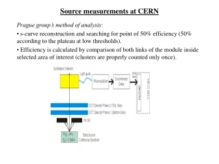
Pressure drop measurements at CERN. Introduction. Purpose: measure pressure drops and HTCs for reasonable pipe diameters Compare to models – understand which model works best for our parameters Start with straight pipes, 3.175mm and 2.2mm OD, later include bends Location

E N D
Introduction • Purpose: • measure pressure drops and HTCs for reasonable pipe diameters • Compare to models – understand which model works best for our parameters • Start with straight pipes, 3.175mm and 2.2mm OD, later include bends • Location • Building 158: CORA cooling plant (used for tests for CMS upgrade and ATLAS IBL) • Planning by Richard B, DUTs prepared by Richard F • Local help from Alex Bitadze. This is what Alex and I did from 9/10 to 11/10: • Setup readout box with NTCs and pressure sensor readout • Take temperature calibration points (not clear whether needed with NTCs) • Connect DUT to CORA • Connect power supply to tube (started with 3.175mm tube) • Test that heating and NTCs work (dry run) • Could not run the plant (no expert available)
Setup • Pressure sensors are 1-100 bar relative • Capillary to one pressure sensor too short – for now connected to spare pressure sensor, should be changed • Additionally: one absolute pressure sensor for atmospheric pressure p2 p1 85cm - + - T1 T2 T3 T4 T5 T6 T7 T8 T9 T10 4 6 5 15 15 15 15 15 5 5 4cm p3 (not used)
Dry run • Set power supply to 5A, measure 0.42V → estimate tube resistance (2 halves parallel) is 0.84Ω • Power supply did cut out arbitrarily • Will replace it with one of Alex’s supplies • Still, could see that tube is heating, and the correct temperature sensors increase Average between 16:45 and 16:50 Power cutting out
Modifications on input • We need a capillary to fix boiling point to start of DUT • This should be instrumented with pressure and temperature sensors before and after to determine state of fluid before (liquid) and after (two-phase vapour quality) • We might also add a heater after the capillary to be able to shift the input vapour quality • Preferably this would require another pressure sensor before the heater (to take out pressure drop in heater) Tliq From plant To gun case Tliq,pliq + pin pliq pin + + p1 Δh
Next steps • When available, add interlock box • Get right length capillary for downstream pressure measurement • Leak checking • Pressurize system and check that relative sensors work accurately, if not calibrate • Run with CO2, do some measurements • Need to revise test matrix • Change to 2.2mm OD tube • When available, insert input capillary and heater • Change to DUTs with bends