Download
1 / 1

E N D
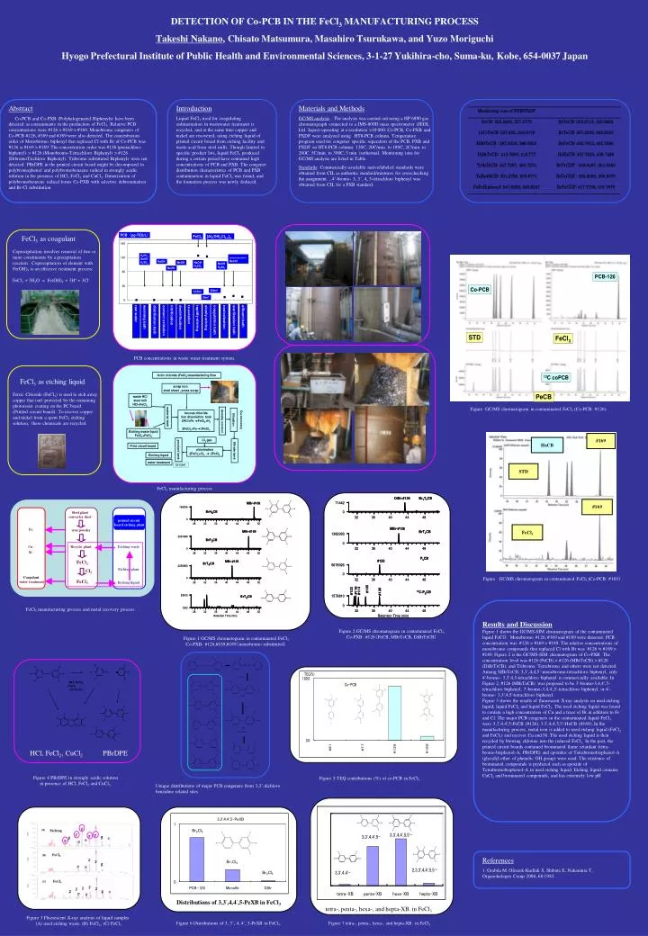
Abstract Co-PCB and Co-PXB (Polyhalogenated Biphenyls) have been detected as contaminants in the production of FeCl3. Relative PCB concentrations were #126 > #169 > #189. Monobromo congeners of Co-PCB #126, #169 and #189 were also detected. The concentration order of Monobromo biphenyl that replaced Cl with Br of Co-PCB was #126 ≒ #169 > #189. The concentration order was #126 (pentachloro biphenyl) > #126 (Monobromo-Tetrachloro Biphenyl) > #126 (DibromoTrichloro Biphenyl). Tribromo substituted Biphenyls were not detected. PBrDPE in the printed circuit board might be decomposed to polybromophenol and polybromobenzene radical in strongly acidic solution in the presence of HCl, FeCl2 and CuCl2. Dimerization of polybromobenzene radical forms Co-PXB with selective debromination and Br-Cl substitution References 1. Grabda M, Oleszek-Kudlak S, Shibata E, Nakamura T, Organohalogen Comp 2006; 68:1983. Materials and Methods GC/MS analysis : The analysis was carried out using a HP 6890 gas chromatograph connected to a JMS-800D mass spectrometer (JEOL Ltd. Japan) operating at a resolution >10 000. Co-PCB, Co-PXB and PXDF were analyzed usingHT8-PCB column. Temperature program used for congener specific separation of the PCB, PXB and PXDF on HT8-PCB column: 120C, 20C/min. to 180C, 2C/min. to 260C. 5C/min. to 300C, 5 min. isothermal. Monitoring ions for GC/MS analysis are listed in Table. Standards: Commercially-available native/labeled standards were obtained from CIL as authentic standard/mixtures for crosschecking the assignment. , 4’-bromo- 3, 3’, 4, 5-tetrachloro biphenyl was obtained from CIL for a PXB standard. Introduction Liquid FeCl3 used for coagulating sedimentation in wastewater treatment is recycled, and at the same time copper and nickel are recovered, using etching liquid of printed circuit board from etching facility and waste acid from steel mills. Though limited to specific product lots, liquid FeCl3 produced during a certain period have contained high concentrations of PCB and PXB. The congener distribution characteristics of PCB and PXB contamination in liquid FeCl3 was found, and the formation process was newly deduced. Steel plantconverter dust printed circuit board etching plant Fe iron powder Cu Recycle plant Etching waste Ni FeCl2 Etching plant Cl2 Coagulant #169 FeCl3 water treatment HxCB Etching liquid STD #169 FeCl3 Distributions of 3,3’,4,4’,5-PeXB in FeCl3 Cu Cu (A) (A) Etching Cu Cu Fe Fe Fe Fe Mn Mn Pb Pb Cr Cr Ni Ni Br Br Zn Zn FeCl2 (B) (B) Fe Fe Fe Fe Mn Mn Zn Zn Ni Ni FeCl3 (C) (C) Fe Fe Cu Cu Fe Fe Cu Cu Pb Pb Mn Mn Cr Cr Zn Zn Ni Ni tetra-, penta-, hexa-, and hepta-XB. in FeCl3 DETECTION OF Co-PCB IN THE FeCl3 MANUFACTURING PROCESS Takeshi Nakano, Chisato Matsumura, Masahiro Tsurukawa, and Yuzo Moriguchi Hyogo Prefectural Institute of Public Health and Environmental Sciences, 3-1-27 Yukihira-cho, Suma-ku, Kobe, 654-0037 Japan FeCl3 as coagulantCoprecipitation involves removal of two or more constituents by a precipitation reaction. Coprecipitation of element with Fe(OH)3 is an effective treatment process: FeCl3 + 3H2O = Fe(OH)3 + 3H+ + 3Cl- PCB concentrations in waste water treatment system. FeCl3 as etching liquidFerric Chloride (FeCl3) is used to etch away copper that isn't protected by the remaining photoresist coating on the PC board (Printed circuit board). To recover copper and nickel from a spent FeCl3 etching solution, these chemicals are recycled. Figure GC/MS chromatogram in contaminated FeCl3(Co-PCB: #126) FeCl3 manufacturing process. Figure GC/MS chromatogram in contaminated FeCl3 (Co-PCB: #169) FeCl3 manufacturing process and metal recovery process. Results and Discussion Figure 1 shows the GC/MS-SIM chromatogram of the contaminated liquid FeCl3. Monobromo #126, #169 and #189 were detected. PCB concentration was #126 > #169 > #189. The relative concentrations of monobromo compounds that replaced Cl with Br was #126 ≒ #169 > #189. Figure 2 is the GC/MS-SIM chromatogram of Co-PXB. The concentration level was #126 (PeCB) > #126 (MBrTeCB) > #126 (DiBrTrCB), and Tribromo, Tetrabromo and others were not detected. Among MBrTeCB; 3,3’,4,4,5’-monobromo-tetrachloro biphenyl, only 4'-bromo- 3,3',4,5-tetrachloro biphenyl is commercially available. In Figure 2, #126 (MBrTeCB) was proposed to be 3'-bromo-3,4,4',5-tetrachloro biphenyl, 3'-bromo-3,4,4',5'-tetrachloro biphenyl, or 4'-bromo- 3,3',4,5'-tetrachloro biphenyl. Figure 3 shows the results of fluorescent X-ray analysis on used etching liquid, liquid FeCl2 and liquid FeCl3. The used etching liquid was found to contain a high concentration of Cu and a trace of Br in addition to Fe and Cl. The major PCB congeners in the contaminated liquid FeCl3 were 3,3',4,4',5-PeCB (#126), 3,3',4,4',5,5'-HxCB (#169). In the manufacturing process, metal iron is added to used etching liquid (FeCl2 and FeCl3) and recover Cu and Ni. The used etching liquid is then recycled by blowing chlorine into the reduced FeCl2. In the past, the printed circuit boards contained brominated flame retardant (tetra-bromo-bisphenol-A, PBrDPE) and epoxides of Tetrabromobisphenol-A (glycidyl-ether of phenolic OH group) were used. The existence of brominated compounds is predicted such as epoxide of Tetrabromobisphenol-A in used etching liquid. Etching liquid contains CuCl2 and brominated compounds, and has extremely low pH Figure 2 GC/MS chromatogram in contaminated FeCl3 Co-PXB: #126(PeCB, MBrTeCB, DiBrTrCB) Figure 1 GC/MS chromatogram in contaminated FeCl3 Co-PXB: #126,#169,#189(monobromo substituted) HCl, FeCl2, CuCl2 PBrDPE Figure 4 PBrDPE in strongly acidic solution in presence of HCl, FeCl2 and CuCl2. Figure 5 TEQ contributions (%) of co-PCB in FeCl3 Unique distributions of major PCB congeners from 3,3’-dichloro benzidine related sites. Figure 3 Fluorescent X-ray analysis of liquid samples (A) used etching waste, (B) FeCl2, (C) FeCl3 Figure 6 Distributions of 3, 3’, 4, 4’, 5-PeXB in FeCl3. Figure 7 tetra-, penta-, hexa-, and hepta-XB. in FeCl3