Download
1 / 13
400 likes | 1.44k Views
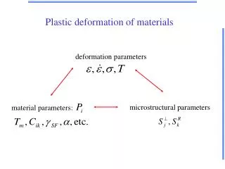
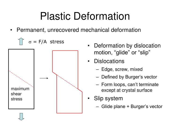
Plastic Deformation. Permanent, unrecovered mechanical deformation. Deformation by dislocation motion, “glide” or “slip” Dislocations Edge, screw, mixed Defined by Burger’s vector Form loops, can’t terminate except at crystal surface Slip system Glide plane + Burger’s vector.

E N D
Plastic Deformation • Permanent, unrecovered mechanical deformation • Deformation by dislocation motion, “glide” or “slip” • Dislocations • Edge, screw, mixed • Defined by Burger’s vector • Form loops, can’t terminate except at crystal surface • Slip system • Glide plane + Burger’s vector s = F/A stress maximum shear stress
a3 a2 b = a/2 <1 1 0> | b | = a/2 a1 [1 1 0] Crystallography of Slip • Slip system = glide plane + burger’s vector • Correspond to close-packed planes + directions • Why? • Fewest number of broken bonds • Cubic close-packed • Closest packed planes • {1 1 1} • 4 independent planes • Closest packed directions • Face diagonals • <1 1 0> • 3 per plane (only positive) • 12 independent slip systems
HCP “BCC” b = a <1 0 0> | b | = a b = a/2 <1 1 1> | b | = 3a/2 • Planes {1 1 0} • 6 independent planes • Directions <1 1 1> • 2 per plane (only positive) • 12 independent slip systems • Planes {0 0 1} • 1 independent plane • Directions <1 0 0> • 3 per plane (only positive) • 3 independent slip systems Occasionally also {1 1 2} planes in “BCC” are slip planes Diamond structure type: {1 1 1} and <1 1 0> --- same as CCP, but slip less uncommon
Why does the number of independent slip systems matter? Are any or all or some of the grains in the proper orientation for slip to occur? s = F/A HCP CCP maximum shear stress • Large # of independent slip systems in CCP at least one will be active for any particular grain • True also for BCC • Polycrystalline HCP materials require more stress to induce deformation by dislocation motion
Dislocations in Ionic Crystals viewing edge dislocations as the termination defect of “extra half-planes” like charges touch 2 1 like charges do not touch long burger’s vector compared to metals compare possible slip planes (1) slip brings like charges in contact (2) does not bring like charges in contact
Energy Penalty of Dislocations bonds are compressed E R0 R compression tension Energy / length |b|2 Thermodynamically unfavorable Strong interactions bonds are under tension attraction annihilation repulsion pinning Too many dislocations become immobile
Summary • Materials often deform by dislocation glide • Deforming may be better than breaking • Metals • CCP and BCC have 12 indep slip systems • HCP has only 3, less ductile • |bBCC| > |bCCP| higher energy, lower mobility • CCP metals are the most ductile • Ionic materials/Ceramics • Dislocations have very high electrostatic energy • Deformation by dislocation glide atypical • Covalent materials/Semiconductors • Dislocations extremely rare Now on to elastic deformation
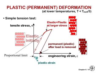
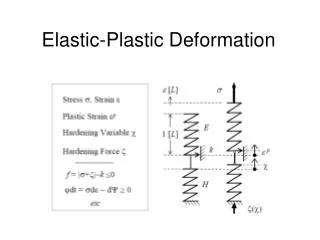
Elastic Deformation • Connected to chemical bonding • Stretch bonds and then relax back • Recall bond-energy curve • Difficulty of moving from R0 • Curvature at R0 • Elastic constants • (stress) = (elastic constant) * (strain) • stress and strain are tensors directional • the elastic constant being measured depends on which component of stress and of strain E R0 R
Elastic Constants Y: Young’s modulus (sometimes E) F stress = uniaxial, normal stress material elongates: l0l A0 strain = elongation along force direction l0 observation: Y s (stress) e (strain) material thins/necks: A0Ai elongates: l0li true stress: use Ai; nominal (engineering) stress: use A0 true strain:use li; nominal (engineering) stress:use l0
Elastic Constants Connecting Young’s Modulus to Chemical Bonding R0 E Hook’s Law R0 F = kDR k / length = Y R stress*area strain*length Coulombic attraction want k in terms of E, R0 observed within some classes of compounds
Elastic Constants Bulk Modulus, K • apply hydrostatic pressure P = F/A s = -P hydrostatic stress • measure change in volume • linear response Can show: analogous to Young’s modulus Coulombic: Useful relationship:
Elastic Constants Poisson’s ratio, n • apply uniaxial stress s = F/A F A • measure e|| - elongation parallel to force • measure e - thinning normal to force e|| e l0 Rigidity (Shear) Modulus, G • apply shear stress t = F/A A Dl • measure shear strain F f = tanf f l0 y F x
Elastic Constants General Considerations Stress, s: 3 3 symmetric tensor 6 parameters Strain, e: 3 3 symmetric tensor 6 parameters In principle, each and every strain parameter depends on each and every stress parameter 36 elastic constants Some are redundant 21 independent elastic constants in the most general case Material symmetry some are zero, some are inter-related Isotropic material only 2 independent elastic constants normal stress only normal deformation shear stress only shear deformation Cubic material G, Y and n are independent