Download
1 / 27
290 likes | 469 Views
Yaesu FT-8800 X-Band Set Up. Step by Step Instructions for Programming Cross Band Operation. Mike Duff NY2PM NY2PM@arrl.net 716-773-2684. Overview.

E N D
Yaesu FT-8800X-Band Set Up Step by Step Instructions for Programming Cross Band Operation Mike Duff NY2PM NY2PM@arrl.net 716-773-2684
Overview • This presentation uses segments of the Yaesu FT-8800R Operating Manual to walk the user through the steps to set up a Yaesu FT-8800 Radio for Cross Band Operation. The following outline will be used: • Training Scenario Definition • Understand the “Main” Indicator • Front Panel Controls & Switches • Turning on the radio • Entering the VFO Mode • Entering a Simplex Frequency • Adding CTCSS Tones • Adjusting the Power Setting • Saving to Memory • Adjusting the Squelch Settings • Entering Cross Band Mode • Programming a Duplex Frequency Pair • Programming an Odd Split Frequency Pair • A Few Words of Caution
Training Scenario Definition • For the purposes of this training session we will propose that hams have been dispatched to local hospitals with their Handie-Talkies. • While communications in the Local Area are possible, the HTs lack the power to communicate between the hospitals in the Wide Area. • The hams have decided to use the FT-8800 at each hospital to set up Cross Band operation such that Local Area HT signals are re-transmitted over a Wide Area VHF circuit to distant hospitals.
Training Scenario Definition • We will use the following set up for our training scenario: • Local Area circuit: • Frequency = 446.000 MHz Simplex • CTCSS = 107.2 Hz • Radio = Left Side • Wide Area circuit: • Frequency = 147.420 MHz Simplex • CTCSS = 183.5 Hz • Radio = Right Side
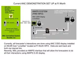
Training Scenario Definition The drawing below represents hams using HTs at local hospitals and employing Cross Banding to link to each other over a Wide Area VHF circuit.
Understandingthe “Main” Indicator • Page 12 of the Yaesu manual introduces the phrase “Main band” without any explanation. • The concept of the “Main band” is the designation of which radio, the left or right, is currently being addressed for purposes of set up or programming and, more importantly, which radio will transmit when the microphone is keyed. • The radio which is operating as the “Main” is indicated by the presence of the symbol in upper right corner of each half of the LCD.
Entering VFO Mode • Select which radio you are going to program by momentarily pressing either the left or right Dial knob (top outside corners) . Make sure that the indicator is displayed in the upper right corner of the appropriate half of the LCD screen. • Press the [V/M] key on the selected side until no Memory Channel number is displayed in the upper left corner of the appropriate half of the LCD screen.
Entering A Simplex Frequency • Use the dial pad on the microphone to enter the desired operating frequency. • You must enter six digits without a decimal point. • For example, to enter 421.000 MHz press [4] →[2] →[1] →[0] →[0] →[0].
Adding CTCSS Tones • Press the [SET] key momentarily to enter the Set Mode. • Rotate the “Main” band DIAL knob to select Menu #41 (TONE M). • Press the “Main” band DIAL knob momentarily to enter the CTCSS Mode sub-menu. • Rotate the “Main” band DIAL knob until “ENC.DEC” appears. Since Decode only is not a choice, we must select ENC.DEC in order to prevent the Squelch from opening except when a valid tone is decoded by our Cross Band Repeater. • Press the “Main” band DIAL knob momentarily to lock in your choice. • Rotate the “Main” band DIAL knob to select Menu #40 (TONE F). • Press the “Main” band DIAL knob momentarily to enter the CTCSS Frequency sub-menu. • Rotate the “Main” band DIAL knob until the display indicates the Tone Frequency you desire. • When you have made your selection, press and hold the “Main” band DIAL knob for ½ second to save your setting and exit to normal operation.
Adjusting the Power Level Adjust the Power Level on both the Local and Wide Area circuits to achieve reliable communications. Remember that good practice is to use only enough power to achieve the desired communications. While the Wide Area circuit may need High Power, the Local Area circuit may work fine on Medium to Low Power.
Saving to Memory • Once the Frequency, CTCSS and Power Levels have been set, it is a good idea to save these to a memory channel . • Press and hold the [SET] key for ½ second. The next blank memory channel will appear blinking in the display. • Press and hold the [SET] key for ½ second to store your set up into this memory channel. • A series of dashes appear to allow you enter an alpha/numeric label for the memory channel. • Press and hold the [SET] key momentarily to skip this function, complete the memory storage procedure and return to normal operation. • Make a note of the memory channel number for future recall.
Adjusting The Squelch Settings The Cross Band function of re-transmitting a signal arriving on one radio’s receiver via the other radio’s transmitter will only occur when the receiving radio’s squelch is opened. Setting the squelch too high will prevent Cross Banding. Setting the squelch too low will result in stray signals being re-broadcast and interfering with Net Operations.
Adjusting The Squelch Settings • We are using the right side of the radio for the Local Area / Handie-Talkie radio circuit and the left side of the radio for the Wide Area radio circuit. • Set the right side Squelch so that transmissions from the HT will open the squelch but stray signals will not. Do likewise with the left side Squelch for the Wide Area circuit. • If you are in a high inter-mod area, you may need to set the squelch settings higher.
Enter Cross Band Mode • Once you have programmed both radios (left and right) and stored their settings into memory, you are ready to enter Cross Band Mode.
Entering a Duplex Frequency Pair • The FT-8800 is pre-programmed to set the mode (Simplex / Duplex) and transmitter offset (600 kHz / 5 MHz) based upon the input frequency via the Automatic Repeater Shift (ARS) feature.
Entering An Odd Split • If your Network Plan requires an Odd Split on Simplex Frequencies (RX is not in a defined Repeater Sub band), you can use the procedure below to enter your frequencies.
A Few Words of Caution • Remember that you are the Control Operator of the Cross Band Radio and are responsible for all transmissions coming from either radio (left or right). • Make sure your Frequencies, CTCSS, Power and Squelch Settings are correct and appropriate. • Make sure you Exit Cross Band mode by pressing the [SET] again to return to normal operation and be sure that the radio is turned off after your drill / activation.