Download
1 / 15
160 likes | 314 Views
Minimizing Micro-Cracks in Solar Cell Interconnections. Paul Wood Advanced Product Applications Manager. Soldering Problems. Solder quality and panel-to- panel consistency Micro-cracks on photovoltaic solar cells Higher temperatures can crack the wafer substrate

E N D
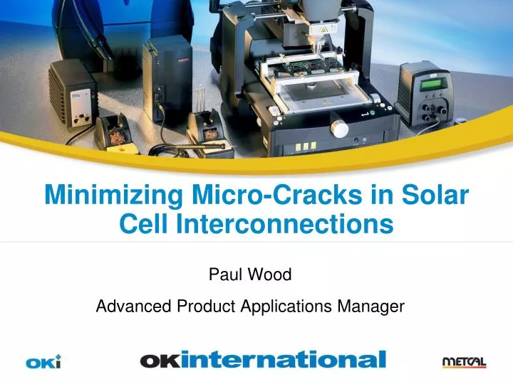
Minimizing Micro-Cracks in Solar Cell Interconnections Paul Wood Advanced Product Applications Manager
Soldering Problems • Solder quality and panel-to- panel consistency • Micro-cracks on photovoltaic solar cells • Higher temperatures can crack the wafer substrate • Pressure can crack wafer substrate usually caused by heater in solder tool cooling • Buss bar tagging or repair is difficult if one panel needs to be replaced
Solar factories still use soldering irons for touch up and rework The flatness and pressure of soldering is still an issue for fully automated lines, so touch up and panel replacement is done by hand soldering. Watch video
Two Soldering Processes: Stringing or Tabbing Bussing Manual Panel Assembly
Solar cell manual assembly soldering video Click here to watch the video
Soldering iron must not overshoot temperature • Solder tip temperature must not overshoot • Is display temperature the actual correct tip temperature? • Having an unstable temperature causes operator variations in pressure. • Temperature self-regulation • No temperature overshoot • Fast thermal response + recovery • High watt density direct power
How to measure repeatability Click here to watch the video
Tip temperature display issue • Display temperature may not be tip temperatures • Up to 60°C difference between display and actual temperature is common at the tips. This is a common fault in conventional solder iron stations and is dangerous to substrate.
Temperature stability and repeatability is critical, do not heat substrate connection temperature over 300°C Micro-cracks are caused by high tip temperatures
How Micro-cracks occur • During the manual soldering operation, differential thermal expansion of the copper and the silicon elements can occur at temperatures greater than 300°C. • This differential can result in the formation of micro-cracks that may not be detected during the manufacturing process and result in a less than expected field lifespan. • The need for precise time and temperature control is additionally critical by the intermetallic layer requirement of 1-2µm that must be created during the solder joint formation.
Buss bar soldering • 4-5mm ribbon is connected at the end of the panel to connect power ribbon. This is a heavier load than stringing operation, which is generally 2-3mm ribbons.
Originally 2mm chisel tips were used by many companies, but they cooled down too fast. OKi developed 2mm hoof tips for ribbon soldering, making it faster and safer. OKi developed 4mm hoof tips for soldering busses faster, with no cooling at tips. Using hoof tips instead of chisel tips is a great improvement Chisel 2 mm 2mm hoof 4mm hoof
OKi manufactures a thermal technology that will produce and maintain a specific self-regulated temperature, with a heater that requires no calibration The heater technology is known as “Curie point heating” Dynamically responds to PV tabbing and bussing thermal loads with measurably improved results Smartheat PS-900 soldering system
Tips are tested for life and repeatability automatically Plating thickness is optimized for performance Too thick iron plate means poor performance, but long life Hoof tips have been developed and proven as ideal for the solar industry Tip life and stability through the life of the tip is critical Watch video
Conclusion • OKi can provide economic solutions with high degree of repeatability • Proven hand soldering application with happy customers within China’s solar industry • Can supply standard equipment or work with OEM manufacturers to give custom solutions