Download
1 / 9
120 likes | 281 Views
Mapping free carrier diffusion in GaAs with radiative and heat-generating recombination Tim Gfroerer and Ryan Crum Davidson College, Davidson, NC with Mark Wanlass National Renewable Energy Lab, Golden, CO ~ Supported by the American Chemical Society – Petroleum Research Fund ~. -. -. -.

E N D
Mapping free carrier diffusion in GaAs with radiative and heat-generating recombinationTim Gfroerer and Ryan CrumDavidson College, Davidson, NCwith Mark WanlassNational Renewable Energy Lab, Golden, CO~ Supported by the American Chemical Society – Petroleum Research Fund ~
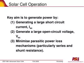
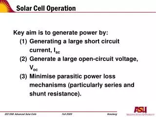
- - - - - + + + + Solar Cell Operation Conduction Band E E - - Field Field HEAT ELECTRON ENERGY ABSORPTION CURRENT PHOTON HOLE E E - - Field Field Valence Band When a photon is absorbed, an electron is excited into the conduction band, leaving a hole behind in the valence band. Some heat is lost, reducing efficiency. Then an internal electric field sweeps the electrons and holes away, creating electricity.
- - + + Light- and Heat-Generating Recombination Conduction Band Conduction Band Defect Level Photon HEAT ENERGY HEAT Valence Band Valence Band Rate ≈ Bx n2(n = carrier density) Rate ≈ A x n (n = carrier density) Electrons can recombine with holes by releasing light or heat. This loss mechanism also reduces the efficiency of a solar cell.
Experimental Setup Laser spot ~ 4 mm diameter Thermal Camera - + + - + - Luminescence Camera - + - + + - + - - + GaAs sample (plan view) - + + - + -
Time evolution of thermal profile Laser on! Heat loss Thermal diffusion
Square-root of the Luminescence Rate ≈ A x n Rate ≈ Bx n2
Conclusions • We use optical and thermal imaging to map the free-carrier density near a localized photo-excitation source. • The density profiles agree when we account for the bimolecular nature of radiative recombination. • BUT: a thermal diffusion calculation also mimics the temperature profile … • So what have we measured?! We’ll figure it out!