Download
1 / 27
270 likes | 326 Views
بسم الله الرحمن الرحيم. An-Najah National University Faculty of Engineering Electrical Engineering. IR Controls Motors. Supervised by: Dr. Ra’ad Jaber. Prepared by: Rayad Hayek. Features. widely application on IR frequency. Transmission distance between Tx&Rx.

E N D
بسم الله الرحمن الرحيم An-Najah National University Faculty of Engineering Electrical Engineering IR Controls Motors Supervised by: Dr. Ra’ad Jaber Prepared by: Rayad Hayek
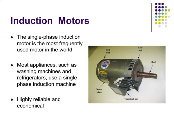
Features widely application on IR frequency Transmission distance between Tx&Rx. Received signal from the wireless camera to the computer.
Reasons for choosing this project IR interest To learn about: infrared transmission IR applications simplicity implementation Wireless control for many devices
IR remote signals Computer control Project diagram microcontroller IR receiver Stepper motor DC motor car camera
Code of IR sender byte Recive() { int flag; int bit1,bit2; int i; byte data; flag =0; restart_wdt(); bit1 = input(PIN_E0); delay_ms(0.026315789473684210526315789473684); bit2 = input(PIN_E0); delay_ms(0.026315789473684210526315789473684); if( bit1==1 && bit2==1) { restart_wdt(); bit1 = input(PIN_E0); delay_ms(0.026315789473684210526315789473684); bit2 = input(PIN_E0); delay_ms(0.026315789473684210526315789473684); if( bit1==1 && bit2==1) { shift_left(&data,1,0); shift_left(&data,1,0); shift_left(&data,1,0); shift_left(&data,1,0); for(i=0;i<4;i++) bit1 = input(PIN_E0); delay_ms(0.026315789473684210526315789473684); bit2 = input(PIN_E0); delay_ms(0.026315789473684210526315789473684); restart_wdt(); { if(bit1== 0 && bit2==1) { //receive zero shift_left(&data,1,0); flag++; } else if(bit1==1 && bit2==0 ) { //receive one shift_left(&data,1,1); flag++; } } } else data='\0'; } else data='\0'; return data; }
Software design software design for IR transmitter to out 4 different signals using C sharp form serial port . There is 4 signals two signals to move the car forward and reverse ,and the other to move it to left or right. Each signal consist of 4 bits to make minimum probability to interference between the signals 1010 0101 1100 0011
IR remote sender IR sender circuit
We work on 38khz frequency on IR sender to make match with IR receiver which work on this frequency. So, we built 555 timer to obtain the frequency because we can’t get it immediately from the serial port of the computer. T1=0.69(R1+R2)C T2=0.69(R2)C T=0.69(R1+2R2)C T=0.69(1k+2*72)*10*10^-9 =2.6e-5 sec F=1/T =1/ 2.6e-5=38khz
And we use max232 IC to regulate the voltage out (-10__+10) (0__5)v
To out the signal to IR LED with f=38khz we sum the two signal (555 timer & max232) to Schmitt trigger that make pulse modulation. 555 timer Serial port
38khz 555timer 1.2khz serial port Out of Schmitt trigger 38khz
We out the signal that we want to control the motors by code in C sharp left, right & up, down . At maximum the distance reach to 20 meters between Tx & Rx , its depend on the power on IR LED and type of the LED.
IR receiver the signal reach to receiver device (TSOP) which connected to microcontroller by the circuit shown. DCD RTS GND
This circuit receive the signal like that out from IR sender with frequency 38k .but with small attenuation ,microcontroller can decide the correct signal
Microcontroller Its wide application device we use it in my project to decide the signal which received from the IR remote to control the motors (DC or stepper)motor by special program.
Microcontroller code SET_TRIS_b(0X00); // TODO: USER CODE!! while(true) { =0; i=Recive(); delay_ms(2); // printf(i); if(i==9){ // Forward output_b (0x01); } // back else if(i==5){ output_b (0x02); } //right else if(i==3){ output_b (0x04); } // left else if(i==7){ output_b (0x08); } } } #include "F:\Car New\ir\Copy of car-test\car.h" #include "F:\Car New\ir\Copy of car-test\WirlessReciver.h" byte i; void main() { setup_adc_ports(NO_ANALOGS|VSS_VDD); setup_adc(ADC_OFF|ADC_TAD_MUL_0); setup_spi(FALSE); setup_wdt(WDT_OFF); setup_timer_0(RTCC_INTERNAL); setup_timer_1(T1_DISABLED); setup_timer_2(T2_DISABLED,0,1); setup_timer_3(T3_DISABLED|T3_DIV_BY_1); setup_comparator(NC_NC_NC_NC); setup_vref(FALSE); setup_low_volt_detect(FALSE); setup_oscillator(False);
DC motor Drive circuit connected to port of microcontroller which make it output port. Drive cct protect the microcontroller from high current and control the motor to return left or right using relay and TIP transistors. We connect the motor to drive the car forward backward because it has more torque than stepper motor.
We can use H bridge IC as drive circuit for DC motor ,its has two drive circuits inside ,we can use it as one drive circuit for stepper motor.
Stepper motor Drive cct protect the microcontroller from high current and control the motor to rotate left or right. We put this motor to steering the car because it has low torque and we can rotate it smoothly.
Drive cct for stepper motor 0 0 1 1 1 1 0 0 Vcc
The wireless camera A video camera catch a video or image from any place which we drive the car. This camera has ready-made program on computer to receive the signal from the camera, it’s has a modulator and receiver hardware or receive the signal by UHF,VHF range on TV
But it not available in the market and very expensive, so we replace it by messenger camera. so, use a USB messenger camera ,its connected to computer immediately by USB cable . Its easy to use and its can capture picture or video. Messenger camera
All drive circuit and the camera built in the car which we control and it carry the camera that take pictures to computer .