Download
1 / 37
400 likes | 484 Views
PCM Principles and Multiplexing. By A.K.Patel SDE (Trans), RTTC, Ahmedabad. Multiplexing. The technique used to provide a number of circuits using a single transmission link is called Multiplexing. Types of Multiplexing. Frequency Division Multiplexing - FDM

E N D
PCM Principles and Multiplexing By A.K.Patel SDE (Trans), RTTC, Ahmedabad
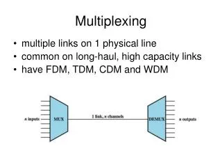
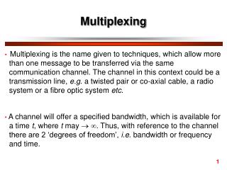
Multiplexing The technique used to provide a number of circuits using a single transmission link is called Multiplexing.
Types of Multiplexing Frequency Division Multiplexing - FDM Time Division Multiplexing - TDM
Time-Domain Concepts • Analog signal - Signal intensity varies in a smooth fashion over time - No breaks or discontinuities in the signal • Digital signal - Signal intensity maintains a constant level for some period of time and then changes to another constant level
Frequency Division Multiplexing • FDM technique is the process of translating individual speech circuits (300-3400 Hz) into pre-assigned frequency slots within the bandwidth of the transmission medium.
Time Division Multiplexing (PCM) • Basically, time division multiplexing is sharing ofa transmission medium by a number of circuits in time domain by establishing a sequence of time slots during which individual channels (circuits) can be transmitted. • Thus the entire bandwidth is periodically available to each channel. • Normally all time slots are equal in length. • Each channel is assigned a time slot with a specific common repetition period called a frame interval.
Pulse- code modulation • PCM is a digital scheme for transmitting analog data. • PCM was invented in the 1920s by P.M. Rainy and rediscovered by. A.H Reeves in 1939
Pulse Code Modulation system It involves five steps : • Filtering • Sampling • Quantization • Encoding • Line Coding
Filtering • Filters are used to limit the speech signal to the frequency band 300-3400 Hz • In simple words, this is performed to filter out the frequencies which are higher than a “certain frequency”.
Sampling • Sampling is the process of creation of a Discrete Signal by taking samples of an Analog Signal at regular intervals. • Sampling is governed by Nyquist Sampling Theorem, according to which when a signal is sampled, fs >= 2fh • Therefore, Fs = 2 x 4000 = 8000 Samples/sec
Sampling creates discrete signals not the digitized signals. Sampling Theorem Fs >= 2Fh
Quantization • It is a process of breaking down a continuous amplitude range into finite number of amplitude values or steps
Two types • Linear Quantization Linear Quantization produce Quantization distortion. In analog-to-digital conversion, the difference between the actual analog value and quantized digital value is called quantization error or quantization distortion • Non –Linear Quantization (Companding) Used in practice to avoid quantization distortion
Encoding • Conversion of Quantized analogue levels to binary signal is called Encoding
To represent 256 steps, 8 level code is required. The • eight bit code is also called an eight bit "word". • The 8 bit word appears in the form • P ABC WXYZ • 1 for +Ve & Segment Code Linear encoding • 0 for -Ve Polarity in the segment • The first bit gives the sign of the voltage to be coded. • Next 3 bits gives the segment number. There are 8 • segments for the positive voltages and 8 for negative • voltages. Last 4 bits give the position in the segment. • Each segment contains 16 positions.
LINE CODING For Digital transmission different medium are used and they have different transmission characteristics like Attenuation, Distortion, Cross talk etc. Also Digital signal it self have strong DC content.
What is line code ? • For distortion free transmission, the PCM output should be converted into a suitable code which will match the characteristics of the medium. This code is called the "line code" and the signal converted to the line code is called a line signal.
TYPES OF LINE CODES • NRZ BINARY CODE. • RZ BINARYCODE. • BIPOLAR CODING (AMI CODE- for 24 Chl PCM system). • HDB3 CODE– for 30 Chl PCM • CMI CODE (CODED MARK INVERSION) • 4B-3T CODE • 5B6B CODE:
Synchronization • The output of a PCM terminal will be a continuous stream of bits. At the receiving end, the receiver has to receive the incoming stream of bits and discriminate between frames and separate channels from these. That is, the receiver has to recognize the start of each frame correctly. This operation is called frame alignment or Synchronization
Contd… • Frame alignment word (FAW) 8 bit inserted into transmitted bit stream at regular Interval. • FAW is transmitted in the TS0 of every alternate frame. • Frame which do not contain the FAW are used for transmitting alarm signals.
Signaling • In a telephone network, the signaling information is used for proper routing of a call between two subscribers, for providing certain status information like dial tone, busy tone, ring back. NU tone, metering pulses, trunk offering signal etc. All these functions are called "signaling" in PCM systems. The signaling information can be transmitted in the form of DC pulses.
Contd….. The signaling pulses retain their amplitude for a much longer period than the pulses carrying speech information. It means that the signaling information is a slow varying signal in time compared to the speech signal. Therefore, a signaling channel can be digitized with less number of bits than a voice channel.
Signaling Contd… • In 30chl PCM TS16 of each frame is used for signaling • 1 ts can carry the signaling data of two channels only hence to carry signaling data of 30 Chls 15 Frames are needed • 1 frame is used to carry syncronisation data for all frames
Multiframe • Hence group of 16 Frames is formed which is called Multiframe • The duration of Frame is 125 Micro second • The Duration of MultiFrame is 2 Milisecond
DIGITAL HIERARCHY BASED ON THE 2048 KBIT/S PCM PRIMARY MULTIPLEX EQUIPMENT
MULTIPLEXING OF SYNCHRONOUS DIGITAL SIGNALS • Block interleaving : Bunch of information taken at a time from each tributary and fed to main multiplex output stream. The memory required will be very large. • Bit interleaving : A bit of information taken at time from each tributary and fed to main multiplex output stream in cyclic order, a very small memory is required.