Download

1 / 51
560 likes | 832 Views
Computer Architecture Pipelined Processor. Ola Flygt Växjö University http://w3.msi.vxu.se/users/ofl/ Ola.Flygt@msi.vxu.se +46 470 70 86 49. Outline. 5.1 Basic concept 5.2 Design space of pipelines 5.3 Overview of pipelined instruction processing

E N D
Computer ArchitecturePipelined Processor Ola Flygt Växjö University http://w3.msi.vxu.se/users/ofl/ Ola.Flygt@msi.vxu.se +46 470 70 86 49
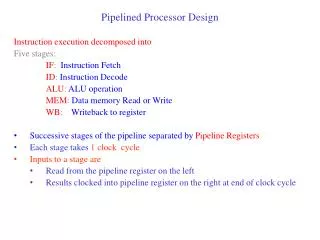
Outline • 5.1 Basic concept • 5.2 Design space of pipelines • 5.3 Overview of pipelined instruction processing • 5.4 Pipelined execution of integer and Boolean instructions • 5.5 Pipelined processing of loads and stores CH01
Processing of a sequence of instructions using a basic pipeline
Structure and pipelined operation of the Fx unit of the IBM Power1
Pipeline Performance Measures • Cycle time: tc • is determined by the worst-case processing time of the longest stage • Repetition Rate: R • the shortest possible time interval between subsequent independent instructions in the pipeline • Performance potential of a pipeline: P P = 1/(R * tc) PowerPC603 FP double Mul. e.g. R = 2, tc = 12 nsec P = 1/(R * tc) = 1/(2*12nec) = 44.6 MFLOPS
Performance: RAW-dependent • Latency: • specifies the amount of time that the result of a particular instruction takes to become available in the pipeline for a subsequent dependent instruction. • Define-use latency (1 to 100 cycles) • mul r1, r2, r3 • add r5, r1, r4 • Load-use latency (1 to 3 cycles, sometimes much more) • load r1, x • add r5, r1, r2 • Stalled: the immediately following RAW-dependent instruction has to be stalled in the pipeline for n-1 cycle
Improve Performance • Multiple-operation instructions • HP PA 7100 FMPYADD RM1, RM2, RM3, RA1, RA2 RM3RM1*RM2 RA2RA1+RA2 • PowerPC FMA for performing (A*C) + B
5.2 Design space of pipelines • key aspect of the design space of pipeline
5.2.2 Basic layout of a pipeline • Design space of the overall stage layout
Increasing parellelism by raising the number of pipeline stages
Problems arise for more stages • data and control dependencies occur more frequently • stalled and wait for data • reload pipe in case of branch • subtask becomes less balances (in execution time) • cycle time is determined by the worst-case processing time of the longest stage • In most case • 5-10 stages
Bypasses (data forwarding in RAW) • Unless special arrangements are made, the results of the operation instruction is written into the register file, or into the memory, and then it is fetched from there as a source operand.
Case studies: Pentium • Logic layout of Pentium’s pipelines
5.4 (Specific) Pipelines execution:Integer and Boolean instructions (FX)
Logical to Physical: e.g. PowerPC601 using a single universal FX unit
Layout of the 5 stages FX and L/S pipelines in the MIPS R4200
Traditional CISC pipeline: The execution of register-memory instruction
CISC pipeline: Execution of register-register and load/store instructions
Handling Load-use delay • Basic approaches to cope with a load-use delay