Download
1 / 35
350 likes | 502 Views
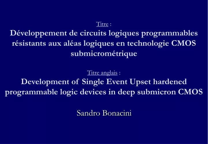
Titre : Développement de circuits logiques programmables résistants aux aléas logiques en technologie CMOS submicrométrique Titre anglais : Development of Single Event Upset hardened programmable logic devices in deep submicron CMOS. Sandro Bonacini. Outline. Motivation and objectives

E N D
Titre :Développement de circuits logiques programmables résistants aux aléas logiques en technologie CMOS submicrométriqueTitre anglais :Development of Single Event Upset hardened programmable logic devices in deep submicron CMOS Sandro Bonacini
Outline • Motivation and objectives • CERN and the LHC • Radiation environment at the LHC • Radiation effects on ICs • Total Ionizing Dose (TID) effects and hardening • Single Event Effects (SEE) • Study on SEU hardening techniques • Design of SEU-robust registers • Experimental results • Design of a radiation-tolerant FPGA • Study on FPGA architectures • Experimental results • Design of a radiation-tolerant PLD
Motivation • Experimental High-Energy Physics (HEP) would benefit from the availability of radiation-hard programmable logic • FPGAs • Fast design development • Flexibility (changing requirements, failure recovery, …) • Possible use as IP-core • PLDs • Glue logic, simple state machines • Hard fixes in the late stages of a project • Commercial devices do not attain radiation levels of inner sub-detectors in LHC’s experiments
Objectives • Programmable logic components • TID-tolerant to experiment upgrades inner tracker levels • Built-in SEU hardness • Configuration bank and user registers… • User can avoid utilization of SEU hardening techniques at HDL level and/or reconfiguration techniques for program restoration • FPGA • SRAM-based, ~25k gates, 256 I/Os • in 0.13μm CMOS • PLD • Fuse-based, 10 inputs, 8 bidirectional • in 0.25μm CMOS
CERN and theLarge Hadron Collider (LHC) • CERN is a particle physics research laboratory run by 20 member states • Currently a new accelerator is being assembled at CERN • the Large Hadron Collider • … whose target is to accelerate protons to an energy of 7 TeV
Experiments at LHC • LHC’s beam pipe runs on a 27-km-long underground tunnel • Four experiments are based on the LHC and are currently being built • The experiments are located around the proton-proton collision points Grenoble
Experiments at the LHC have a considerable size Several stories high, tens of meters long Composed by several sub-detectors Cover ~all directions from interaction point People standing in superconducting coil at 100K Example of an LHC experiment:the Compact Muon Solenoid
At peak luminosity, up to 1015 cm-2 hadrons in 10 years of operation Simulations performed with FLUKA Fluence of neutrons (>100keV) and charged hadrons in cm–2 >1015 >3.2·1014 1015> >1014 3.2·1014> 5.2 m 2.6 m 1014> >3.2·1013 >1013 3.2·1013> 1013> >3.2·1012 >1012 3.2·1012> >3.2·1011 1012> >1011 3.2·1011> 1011> Fluence of hadrons in CMS inner sub-detectors 7.3 m
Up to 35 Mrad in 10 years of operation at peak luminosity Dose rate up to 1.5 krad/h 5.2 m 2.6 m Radiation total dose in rad >107 107> >106 >105 106> 105> >104 >103 104> >102 103> 102> Total Ionizing Dosein CMS inner sub-detectors 7.3 m
In order avoid these conductive paths it is possible to use (in nMOS transistors) Enclosed Layout Transistors p+ guard rings TID induces Threshold voltage shift Minor issue in deep submicron devices Leakage current increase in nMOS due to the accumulation of positive charge in the field oxide which induces conductive paths in the substrate Total dose effects on MOS transistors and solutions
1 . E - 03 0 . 25 µm 1 . E - 04 Standard 1 . E - 05 1 . E - 06 ) A ( 1 . E - 07 k a e 1 . E - 08 L 1 . E - 09 ELT 1 . E - 10 1 . E - 11 1 . E - 12 10 100 1000 10000 Dose ( krad ( SiO 2 )) 60 40 20 [mV] 0 th V -20 D NMOS, L=0.28 -40 PMOS, L=0.28 -60 -80 1.E+03 1.E+04 1.E+05 1.E+06 1.E+07 1.E+08 Annealing Total Dose [rad(SiO )] 2 ELT vs linear transistors 0.25 micron 0.13 micron Leakage current Threshold voltage shift
Total Ionizing Dose hardening • Design practices for TID hardening • 0.25μm CMOS technology • Enclosed Layout Transistors • Guard-rings • 0.13μm CMOS technology • Sufficiently TID-hard for digital logic without ELT • Faccio and Cervelli, “Radiation-induced edge effects in deep submicron CMOS transistors”,IEEE Transactions on Nuclear Science, vol. 52, December 2005 • Use of linear transistors with W>0.30μm O.25 micron O.13 micron
Single-Event Effects (SEEs) • Effects due to a single ionizing particle crossing the device • Single-Event Latchup • destructive effect which can occur because of the parasitic thyristor formed by the junction structure present in CMOS ICs • Deep submicron technologies are becoming less susceptible (low supply voltage, highly doped substrate, trench isolation between wells, …) • Single-Event Upset • Non-destructive effect which alters the data stored in a memory circuit by deposition of charge in the circuit nodes • … gate rupture, snapback, burnout …
An ionizing particle creates electron-hole pairs which are collected by the electric field of junctions The voltage on the node connected to the junction changes In a typical SRAM cell if 1 of the 2 memory nodes is brought above/below Vdd/2 the stored value is corrupted Single-Event Upsets (SEUs)
Single-Event Transients (SETs) 1 • SEUs can also be generated indirectly by a particle hit in the combinatorial logic which creates a transient pulse propagating through the datapath • If the pulse reaches the FF during the closing edge of the clock the data is corrupted • SET-induced-SEU rate is proportional to clock frequency
Study on SEU hardening • Several ways to protect memories against SEUs • System-level techniques • Triple Module Redundancy (TMR) • Error Correction Coding (ECC) • Circuit-level techniques • Dual-Interlocked Cell • Whitaker cell • Dooley, Rocket, SERT, … • Device-level techniques • Capacitance increase, threshold voltage control, …
Hamming Encoding • Tolerates 1 error over n bit • Efficient coding • log2(n + 1) additive bits on n-bit codewords • Encoder/decoder is necessary • Logic complexity grows as O(nlogn) • Suitable for big RAM blocks • 1 enc/dec for a whole memory • Needs refresh routine • Not suitable for FPGAs • All data must be accessible at all times… • … would need huge enc/dec • Difficult implementation of protection against SETs Combinatoriallogic Encoder Registers Decoder
Triple Module Redundancy • Triplicate registers and use a majority voter to decode • Better protection than ECC • Tolerates 1 error over 3 bit • Less efficient than ECC • 3x area and power • Protection against SETs • Redundant combinatorial logic • Suitable for high-speed applications
4 memory nodes Each memory node is correlated to 2 other memory nodes Interlock Symmetric cell Each node is equivalent to the others 2 stable states (1,0,1,0) (0,1,0,1) pMOS propagate right only low values nMOS propagate left only high values T. Calin, M. Nicolaidis & R. Velazco. “Upset Hardened Memory Design for Submicron CMOS Technology”. IEEE Transactions on Nuclear Science, vol. 43, no. 6, pages 2874-2878, December 1996. Intrinsically immune to single-node particle hits Vulnerable to multiple-node particle hits Dual-Interlocked Cell (DICE) - 1 1z 0z 1 0 1 0 A B C D
Choice for SEU hardening: DICE • Using a SEU-robust register circuit gives the best trade-off between area occupancy and SEU tolerance • The DICE is the smallest SEU-robust cell • 12 transistors per memory cell • 2x with respect to a traditional SRAM cell • Smaller area than TMR (3x) • Better protection than ECC C D A B
Fully 2× redundant 2 inputs 2 outputs 2 clock buffers Normally they have the same logic levels ck0 D0 Q0 ck0n ck1n ck0n A B C D ck1 ck0 ck1 D1 Q1 ck1n SEU-robust latch …add clock driven transmission gates to access memory nodes… C D A B
SA & output buffer clock buffer MB SB clock buffer MA SC & output buffer clock buffer MD SD clock buffer MC ck0 ck0n D0 MC MA SC SA MB ck0n Q0 ck1n ck0n MD SB ck0 ck1 SD ck0 ck1 ck0 ck1n ck0n ck1 ck1n D1 ck1n Q1 ck1 Register layout for SEU robustness • SEU-register is composed by a master latch and a slave latch • Master nodes: MA, MB, MC, MD • Slave nodes: SA, SB, SC, SD • Latch is vulnerable to multiple-node particle hits on correlated nodes • The nodes of the two latches are interleaved in order to increase the distance between correlated nodes • Less probability of multiple-node particle hit
Duplicate combinatorial logic Use SEU-robust FF SEU-robust FF has 2 inputs and 2 outputs Can tolerate an SEU on one of the two inputs. Duplicate data path alleviates the problem of latching erroneous states Protection against Single-Event Transients (SETs) Which occur in combinatorial logic and propagate to the flip-flops FF FF Combinatorial Logic FF SET protection: duplicated logic Non SET-robust SET-robust SEU-R FF Combinatorial Logic SEU-R FF Combinatorial Logic SEU-R FF
Static shift-register test Stream in configuration Beam start/stop Retrieve configuration & compare Dynamic shift-register test Continuous configuration load, retrieve & compare while configuration clock is running and beam is on Two test chips were fabricated 0.25μm CMOS 2×2 mm2, 1024 SEU-robust registers 0.13μm CMOS 1×2 mm2, 9216 SEU-robust registers, 4096 standard library registers Heavy-ion beam testson SEU-robust register USB interface Test controller Device Under Test (back)
Test chip in 0.25μm CMOS • Test results: • SEU robustness of the register cell up to an LET of 79.6 cm2MeV/mg • no errors observed in either static and dynamic test modes • At an LET of 112 cm2MeV/mg and only in the dynamic test mode, the register cell showed SEU sensitivity, with SEU cross-section of 6.2·10-10 cm2/bit • LHC environment: LET up to 17 cm2MeV/mg • Huhtinen and Faccio, “Computational method to estimate Single Event Upset rates in an accelerator environment”, Nuclear Instruments and Methods in Physics Research A 450 (2000) 155-172 • For comparison: standard cell flip-flop in same technology has LETth=14.7cm2MeV/mg and σsat =2.59·10-7 cm2/bit
Test chip in 0.13μm CMOS • 0.13μm CMOS • Good static mode robustness • no errors up to 45.8 cm2MeV/mg • In dynamic mode register shows sensitivity • strongly dependent on angle of incidence of the beam • Suitable as configuration register • Not suitable as user register
Comparison of SEU-robust registers in 0.25μm and 0.13μm CMOS
FPGAs differ on Granularity size and implementation capability of the Logic Block (LB) Routing structure Island-style Sea-of-gates I/O signaling capabilities Programming technique SRAM, fuses, Flash, … Special-purpose blocks Multipliers, block RAM, PLL/DLLs, processor cores, … Study on FPGA architectures
Best granularity 4-input-1-output Look-Up Table (LUT) implements any boolean function of 4 variables holds its truth table in 16 configuration registers can also be used as a 16×1-bit RAM block 31 configuration bits per LB are present and are organized in a shift-register structure SEU-R FF Logic Block COUT Carry chain D YQ A[0] 4-input LUT Y A[1] A[2] A[3] CLK CIN S/R
long local double long clock YQAin YAin Tin RESout B1out A1out long local double long vdd YQB YQBout B[3] A[3] SET A[0] YB YBout A2out B[0] A[2] LB A2in B2out DA pair B[2] DBout B2in CLK DB DBin YQA RES B[1] A[1] YA YQBin YBin RESin B1in A1in YAout YQAout Tout Programmable interconnections • Hierarchical routing • LB has 17 I/Os • 18 wires per direction • 6 long lines • 12 short-distance lines • 8 direct neighbor connections • Connections implemented with • tristate buffers • transmission gates • multiplexers • 256 configuration registers in total
Typical FPGA architecture Array of 32×32 Logic Blocks (LBs) Configurable routing SRAM based Reprogrammable 256 I/Os ~25k equivalent gates 2560 total user F/Fs Possible use as IP-core Radiation-tolerant FPGA Logicblock Logicblock Logicblock Logicblock Logicblock Logicblock Logicblock Logicblock Logicblock
Test chip for Logic Block • A test chip was fabricated in 0.25 micron CMOS • Containing 32 LBs organized in 4 modules • No programmable interconnections • Hardwired connections • Cascaded LBs • SEU/SET testing performed • Heavy-ion beam • All LBs configured as 4-way registered XOR • Clocked at 25 MHz • Pseudo-random data input • No errors observed • σ ≤ 9.4·10-8 cm2/bit
Ap … A2 A1 … M1 M2 M3 M4 M6 M5 M7 M8 … … Mn-3 Mn-2 Mn-1 Mn … OL OL OL CLK … Qp Q2 Q1 Radiation-tolerant PLD • Compatible with 16LV8 commercial device • Fuse based • Laser programmable • 10 inputs, 8 programmable input/outputs • Configurable AND matrix generates minterms • Fixed OR matrix sums minterms • 8 minterms per output • Outputs can be registered or not • Outputs are fed back to AND matrix for generation of more complex functions
Fuses & PLD chip layout • Fuses consist in a 7×1 μm2 metal line (aluminum) • Laser programmable • 2080 programming fuses • Occupy 70% of core area • Chip size is 2×2 mm2 laser
Conclusions • An SEU-robust register structure was designed and tested in two CMOS technologies • Results obtained in the 0.25 μm technology demonstrate the register is suitable for the implementation of programmable logic • The 0.13 μm circuit showed good robustness in the static tests but appeared to be sensitive in the dynamic tests • Suitable for configuration storage • Additional work is necessary for the FPGA user register • The approach demonstrated the feasibility of the SEU-tolerant radiation-hard PLD and FPGA • PLD chip was fabricated and tested • The LB of the FPGA design was finalized, work is on going to complete the FPGA with interconnection infrastructure