Download

1 / 19
200 likes | 331 Views
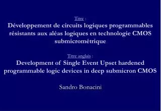
Development of SEU-robust, radiation-tolerant and industry-compatible programmable logic components. Sandro Bonacini CERN. Outline. Motivation and objectives TID hardening SEU hardening Experimental results for SEU-robust structures PLD design description FPGA design description.

E N D
Development of SEU-robust, radiation-tolerant and industry-compatible programmable logic components Sandro Bonacini CERN
Outline • Motivation and objectives • TID hardening • SEU hardening • Experimental results for SEU-robust structures • PLD design description • FPGA design description Sandro BONACINI
Motivation • High-Energy Physics would benefit from the availability of radiation-hard programmable logic • FPGAs • Fast design development • Flexibility (changing requirements, failure recovery, …) • PLDs • Glue logic, simple state machines • Hard fixes in the late stages of a project • Commercial devices do not attain LHC radiation levels • >30 Mrad total dose • SEUs from intense flux of hadrons • ~1015 hadrons/cm2 in 10 years LHC Sandro BONACINI
Objectives • Programmable logic components • TID-tolerant to experiment upgrades inner tracker levels • Built-in SEU hardness • Configuration bank and user registers… • …protected at circuit level against SEUs • User can avoid utilization of SEU hardening techniques at HDL level and/or reconfiguration techniques for program restoration • FPGA • compatible with an existing device, ~25k gates, 256 I/Os • in 0.13μm CMOS • PLD • compatible with 16LV8 device, 10 inputs, 8 bidirectional • in 0.25μm CMOS Sandro BONACINI
Total Ionizing Dose hardening • Design practices for TID hardening • 0.25μm CMOS technology • Enclosed Layout Transistors • Guard-rings • 0.13μm CMOS technology • Sufficiently TID-hard for digital logic without ELT • Faccio and Cervelli, “Radiation-induced edge effects in deep submicron CMOS transistors”,IEEE Transactions on Nuclear Science, vol. 52, December 2005 • Use of linear transistors with W>0.30μm O.25 micron O.13 micron Sandro BONACINI
SEU-R FF Single-Event Upset hardening • Circuit level SEU protection • SEU-robust register • used for configuration storage • …and user data • Based on Dual-Interlocked Cell (DICE) • Protection against Single-Event Transients (SETs) • Which occur in combinatorial logic • Duplication Sandro BONACINI
4 memory nodes Each memory node is correlated to 2 other memory nodes Interlock Symmetric cell Each node is equivalent to the others 2 stable states (1,0,1,0) (0,1,0,1) pMOS propagate right only low values nMOS propagate left only high values Intrinsically immune to single-node particle hits Vulnerable to multiple-node particle hits Dual-Interlocked Cell (DICE) - 1 1z 0z 1 0 1 0 A B C D Sandro BONACINI
Fully 2× redundant 2 inputs 2 outputs 2 clock buffers Normally they have the same logic levels ck0 D0 Q0 ck0n ck1n ck0n A B C D ck1 ck0 ck1 D1 Q1 ck1n SEU-robust latch …add clock driven transmission gates to access memory nodes… C D A B Sandro BONACINI
SA & output buffer clock buffer MB SB clock buffer MA SC & output buffer clock buffer MD SD clock buffer MC ck0 ck0n D0 MC MA SC SA MB ck0n Q0 ck1n ck0n MD SB ck0 ck1 SD ck0 ck1 ck0 ck1n ck0n ck1 ck1n D1 ck1n Q1 ck1 Register layout for SEU robustness • SEU-register is composed by a master latch and a slave latch • Master nodes: MA, MB, MC, MD • Slave nodes: SA, SB, SC, SD • Latch is vulnerable to multiple-node particle hits on correlated nodes • The nodes of the two latches are interleaved in order to increase the distance between correlated nodes • Less probability of multiple-node particle hit Sandro BONACINI
Duplicate combinatorial logic Use SEU-robust FF SEU-robust FF has 2 inputs and 2 outputs Can tolerate an SEU on one of the two inputs. Duplicate data path alleviates the problem of latching erroneous states Protection against Single-Event Transients (SETs) Which occur in combinatorial logic and propagate to the flip-flops FF FF Combinatorial Logic FF SET protection: duplicated logic Non SET-robust SET-robust SEU-R FF Combinatorial Logic SEU-R FF Combinatorial Logic SEU-R FF Sandro BONACINI
Static shift-register test Stream in configuration Beam start/stop Retrieve configuration & compare Dynamic shift-register test Continuous configuration load, retrieve & compare while configuration clock is running and beam is on Two test chips were fabricated 0.25μm CMOS 2×2 mm2, 1024 SEU-robust registers 0.13μm CMOS 1×2 mm2, 9216 SEU-robust registers, 4096 standard library registers Heavy-ion beam testson SEU-robust register USB interface Test controller Device Under Test (back) Sandro BONACINI
Test chip in 0.25μm CMOS • Heavy-ion beam testing • Strong SEU robustness of the register cell up to an LET of 79.6 cm2MeV/mg • no errors observed in either static and dynamic test modes • At an LET of 112 cm2MeV/mg and only in the dynamic test mode, the register cell showed SEU sensitivity, with SEU cross-section of 6.2· 10-10 cm2/bit • LHC environment: up to 17 cm2MeV/mg • Huhtinen and Faccio, “Computational method to estimate Single Event Upset rates in an accelerator environment”, Nuclear Instruments and Methods in Physics Research A 450 (2000) 155-172 Sandro BONACINI
Test chip in 0.13μm CMOS • 0.13μm CMOS • Good static mode robustness • no errors up to 45.8 cm2MeV/mg • In dynamic mode register shows sensitivity • strongly dependent on angle of incidence of the beam • Suitable as configuration register • Not suitable as user register Sandro BONACINI
Ap … A2 A1 … M1 M2 M3 M4 M6 M5 M7 M8 … … Mn-3 Mn-2 Mn-1 Mn … OL OL OL CLK … Qp Q2 Q1 Radiation-tolerant PLD • Compatible with 16LV8 commercial device • Fuse based • Laser programmable • 10 inputs, 8 programmable input/outputs • Configurable AND matrix generates minterms • Fixed OR matrix sums minterms • 8 minterms per output • Outputs can be registered or not • Outputs are fed back to AND matrix for generation of more complex functions Sandro BONACINI
Fuses & PLD chip layout • Fuses consist in a 7×1 μm2 metal line (aluminum) • Laser programmable • 2080 programming fuses • Occupy 70% of core area • Chip size is 2×2 mm2 Sandro BONACINI
Typical FPGA architecture Array of 32×32 Logic Blocks (LBs) Configurable routing SRAM based Reprogrammable 256 I/Os Compatible with an existing commercial device Same design tools can be reused Synthesis, Place & Route Logicblock Logicblock Logicblock Logicblock Logicblock Logicblock Logicblock Logicblock Logicblock Radiation-tolerant FPGA Sandro BONACINI
SEU-R FF Logic Block • 4-input-1-output Look-Up Table (LUT) • implements any boolean function of 4 variables • holds its truth table in 16 configuration registers • can also be used as a 16×1-bit RAM block • 31 configuration bits per LB are present and are organized in a shift-register structure COUT Carry chain D YQ A[0] 4-input LUT Y A[1] A[2] A[3] CLK CIN S/R Sandro BONACINI
long local double long clock YQAin YAin Tin RESout B1out A1out long local double long vdd YQB YQBout B[3] A[3] SET A[0] YB YBout A2out B[0] A[2] LB A2in B2out DA pair B[2] DBout B2in CLK DB DBin YQA RES B[1] A[1] YA YQBin YBin RESin B1in A1in YAout YQAout Tout Programmable interconnections • 18 wires per direction • 6 long lines • 12 short-distance lines • 8 direct neighbor connections • Connections implemented with • tristate buffers • transmission gates • multiplexers • 256 configuration registers in total Sandro BONACINI
Conclusions • An SEU-robust register structure was designed and tested in two CMOS technologies • Results obtained in the 0.25 μm technology demonstrate good robustness of the circuit up to 79.6 cm2MeV/mg • The 0.13 μm circuit showed good robustness in the static tests but appeared to be sensitive in the dynamic tests • Additional work is necessary for the FPGA user register • Our approach demonstrated the feasibility of the SEU-tolerant radiation-hard PLD and FPGA • PLD chip was fabricated • The LB of the FPGA design was finalized, work is on going to complete the FPGA with interconnection infrastructure Sandro BONACINI