Download
1 / 76
760 likes | 767 Views
Chapter 4.1 The Integration : TCP/IP. Telecommunications Concepts. Contents. The internet concept Version 4 Internet Protocols IP addressing IP headers CIDR ICMP The transport layer The Transmission Control Protocol The User Datagram Protocol Network Address Translation

E N D
Chapter 4.1 The Integration : TCP/IP TelecommunicationsConcepts
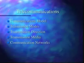
Contents • The internet concept • Version 4 Internet Protocols • IP addressing • IP headers • CIDR • ICMP • The transport layer • The Transmission Control Protocol • The User Datagram Protocol • Network Address Translation • Version 6 Internet Protocol • Side track : IP routing
Contents • The internet concept • Version 4 Internet Protocols • IP addressing • IP headers • CIDR • ICMP • The transport layer • The Transmission Control Protocol • The User Datagram Protocol • Network Address Translation • Version 6 Internet Protocol • Side track : IP routing
Applications Layer The Internet & Transport Layer Transport Layer Internet Layer Networks Layer
Modern data communications require connectivity through many different networks Existing networks offer diverse services levels (Connectionless/Connection Oriented) interfaces with transport layer An Interface layer (the INTERNET layer) is added on top of the Network layers The INTERNET layer ensures Uniform addressing through all networks Well defined and identical services from all networks A common interface with the Transport layer. The Internet Sublayer
In the OSI Community : Less performing networks are enhanced Additional sublayer between network and internet layers : The Enhancement Sublayer. Most often, Connection oriented, Reliable. Inspired by X25 In the Internet Community (Internet Protocol): Minimal Internet Service definition Service restricted to whatever all networks can do : Connectionless, Unreliable Inspired by Local Area Networks The Internet SublayerDesign Philosophy
The Internet Sublayer OSI approach Application 1 Application 2 Application 3 TP0-4 Internet Sublayer Enh Enh Enh any network
The Internet SublayerIP approach Application 1 Application 2 Application 3 TCP UDP Internet Protocol any network
Internet-wide uniform addressing. Two part addresses Network : identifies the network Host : identifies host on a specific network. Host part = subnet identifier + host identifier ) Connectionless, unreliable datagram service Fragmentation when required by network Routing through the entire Internet. Elimination of “lost” datagrams Debugging facilities Special transmission modes Original IP Services
Contents • The internet concept • Version 4 Internet Protocols • IP addressing • IP headers • CIDR • ICMP • The transport layer • The Transmission Control Protocol • The User Datagram Protocol • Network Address Translation • Version 6 Internet Protocol • Side track : IP routing
IP Networks ISDN/PSTN Leased Line LAN Router WAN
Unicast, Multicast and Broadcast Unicast Multicast Broadcast
Distribute information to a group of selected users without overly taxing a networks’ resources Deliver ONE COPY of a datagram to all subnetworks to which group members are attached Definition of Multicast host group Class D multicast addresses A mechanism to JOIN and LEAVE a multicast group sender or receiver based control of group membership protocols to transmit and manage the group membership info throughout the network Internet multicasting
Class A : 0 Net (7) Host (24) 126 networks with up to 16 million hosts each Class B : 10 Net (14) Host (16) 16382 networks with up to 65534 hosts each Class C : 110 Net (21) Host (8) 2 million networks with up to 254 hosts each IP v4 addresses • Four different address formats Class D : 1110 Predefined Multicast groups(28) • Net/Host = all 0’s : Unknown address • Net/Host = all 1’s : Broadcast
Class A : 0 Net (7) Host (24) Class B : 10 Net (14) Host (16) Class C : 110 Net (21) Host (8) IP v4 addressesSome Examples MIT... : INFOS1 : WWW.IEEE 00010010 18. 10000110 134. 11000111 199. xxxxxxxx xxx. 10111000 184. 10101100 172. xxxxxxxx xxx. 00000001 1. 10001000 136. xxxxxxxx xxx 01111101 125 00000001 1
Complete routing tables impossible in large networks Hierarchical routing is the solution Routing table restricted to one level of hierarchy Routing in large networks
Host number can be split :Subnet+ Host Length of actual host number given by mask MASK 11111111 11111111 11111111 11100000 MASK 255 . 255 . 255 . 224 Each subnet in example : 30 hosts (32 - 2) IP v4 Subnetting(example on Class C network 195.1.1) 1 1 0 Network number Subnet Host 21 bits 3 bits 5 bits Subnet number Addresses Broadcast address 32 (001) 195.1.1.33 - 195.1.1.62195.1.1.63 64 (010) 195.1.1.65 - 195.1.1.94195.1.1.95 96 (011) 195.1.1.97 - 195.1.1.126195.1.1.127
Subnet : 195.1.1.96 Subnet : 195.1.1.64 Subnet : 195.1.1.32 Broadcast: 195.1.1.63 Broadcast: 195.1.1.127 Broadcast: 195.1.1.95 IP v4 Subnetting( Example : the 195.1.1.0 / 27 Network) To the Internet (Network 195.1.1.00) 195.1.1.33/27 195.1.1.34/27 195.1.1.65/27 195.1.1.66/27 A D B C 195.1.1.98/27 195.1.1.97/27 Remark : In the notation xxx.xxx.xxx.xxx / n n gives the number of 1’s in the mask F E
Contents • The internet concept • Version 4 Internet Protocols • IP addressing • IP headers • CIDR • ICMP • The transport layer • The Transmission Control Protocol • The User Datagram Protocol • Network Address Translation • Version 6 Internet Protocol • Side track : IP routing
Header Checksum Source IP Address Destination IP Address Options Padding IP v4 datagram format IP header IP Data Area Ver Len Typ.Ser. Total Length Fl. Ident Frag.Offset TTL Proto
IP v4 Header (1) Ver Len Typ.Ser. Total Length Fl. Ident Frag.Offset TTL Proto Header Checksum Source IP Address Destination IP Address Options Padding Ver : Protocol version, incompatible datagrams are rejected. Len: Length of header, in 32 bit words. Tot.Length: Length, in bytes, of the entire datagram.
Header Checksum Source IP Address Destination IP Address Options Padding IP v4 Header (2) Ver Len Typ.Ser. Total Length Fl. Ident Frag.Offset TTL Proto Typ.Serv.: Precedence (0 = normal, 7 = control) D = Short delay wanted (best effort) T = High throughput wanted (best effort) R = High reliability wanted (best effort)
IP header IP Data Area IP header Fragment 1 IP header Fragment 2 IP datagram fragmentation - Packet size exceeds maximum size in network - Excessive delay jitter due to long packets
Header Checksum Source IP Address Destination IP Address Options Padding IP v4 Header (3) Ver Len Typ.Ser. Total Length Fl. Ident Frag.Offset TTL Proto Ident : Unique identifier of fragmented datagram. Fl: “Do not fragment” bit. “More fragments” bit. Frag.Offset: Offset of segment in original datagram.
IP v4 Header (4) Ver Len Typ.Ser. Total Length Fl. Ident Frag.Offset TTL Proto Header Checksum Source IP Address Destination IP Address Options Padding TTL : Time To Live (decremented at each node) Datagram discarded when TTL = 0. Proto: Identifies the higher layer protocols. HdrCks: Redundant error detection bits for header.
IP v4 Header (5) Ver Len Typ.Ser. Total Length Fl. Ident Frag.Offset TTL Proto Header Checksum Source IP Address Destination IP Address Options(var. length) Padding Options :Debuging and special transmission modes copy : Option field reproduced in all fragments class : 0 = datagram or network control 2 = debuging and measurement number : specifies the function of the option
Class 0 Length Option 1 : End of option list 1 2 : Security and handling restrictions 11 3 : Loose Source Routing var 7 : Record route var 9 : Strict Source Routing var Class 2 Option 4 : Internet timestamp var IP v4 Options
Contents • The internet concept • Version 4 Internet Protocols • IP addressing • IP headers • CIDR • ICMP • The transport layer • The Transmission Control Protocol • The User Datagram Protocol • Network Address Translation • Version 6 Internet Protocol • Side track : IP routing
Routing = transmission of a datagram from a “source IP address” to a “destination IP address” Direct Routing Current and destination addresses on same network Direct delivery to destination Indirect Routing Current and destination addresses on different networks Datagram forwarded from source to destination via routers Routers have an address in at least two networks Routing
IP Networks Router 4.2 4.1 1.2 3.2 4.3 1.1 3.3 1.3 5.2 2.1 1.4 5.1 2.2 5.3 6.1 7.2 7.1 2.3 6.2
IF destination net is directly connected THEN (* Direct Routing *) encapsulate datagram in network frame; send frame to destination; ELSE (* Indirect Routing *) with “destination net” as index in local routing table, find address of local router appropriate for reaching that net; encapsulate datagram in network frame; send frame to selected local router; END (* IF *) Routing
Dest.net Forw.to 2.3 IP Networks 1.2 > 7.2 4.2 4.1 1.2 3.2 4.3 1.1 3.3 1.3 5.2 2.1 1.4 5.1 2.2 5.3 6.1 7.2 1 #1 direct 1.1 7.1 6.2
Dest.net Forw.to 2.3 IP Networks 1.2 > 7.2 4.2 4.1 1.2 3.2 4.3 1.1 3.3 1.3 5.2 2.1 1.4 5.1 2.2 5.3 6.1 7.2 1,2,3 4 >4 direct 3.2 2.2 7.1 6.2
Dest.net Forw.to 2.3 IP Networks 1.2 > 7.2 4.2 4.1 1.2 3.2 4.3 1.1 3.3 1.3 5.2 2.1 1.4 5.1 2.2 5.3 6.1 7.2 2,5,6 1,3,4 7 direct 2.1 5.3 7.1 6.2
Dest.net Forw.to 2.3 IP Networks 1.2 > 7.2 4.2 4.1 1.2 3.2 4.3 1.1 3.3 1.3 5.2 2.1 1.4 5.1 2.2 5.3 6.1 7.2 5,7 1,3,4 2,6 direct 5.2 5.1 7.1 6.2
Dest.net Forw.to 2.3 IP Networks 7.2 > 1.2 4.2 4.1 1.2 3.2 4.3 1.1 3.3 1.3 5.2 2.1 1.4 5.1 2.2 5.3 6.1 7.2 7 #7 direct 7.1 7.1 6.2
Dest.net Forw.to 2.3 IP Networks 7.2 > 1.2 4.2 4.1 1.2 3.2 4.3 1.1 3.3 1.3 5.2 2.1 1.4 5.1 2.2 5.3 6.1 7.2 5,7 1,3,4 2,6 direct 5.2 5.1 7.1 6.2
Dest.net Forw.to 2.3 IP Networks 7.2 > 1.2 4.2 4.1 1.2 3.2 4.3 1.1 3.3 1.3 5.2 2.1 1.4 5.1 2.2 5.3 6.1 7.2 3,4,5 1,2 6,7 direct 3.3 5.1 7.1 6.2
Dest.net Forw.to 2.3 IP Networks 7.2 > 1.2 4.2 4.1 1.2 3.2 4.3 1.1 3.3 1.3 5.2 2.1 1.4 5.1 2.2 5.3 6.1 7.2 1,2,3 4 >4 direct 3.2 2.2 7.1 6.2
Contents • The internet concept • Version 4 Internet Protocols • IP addressing • IP headers • CIDR • ICMP • The transport layer • The Transmission Control Protocol • The User Datagram Protocol • Network Address Translation • Version 6 Internet Protocol • Side track : IP routing
Problems with class based addressing : Too few Class B networks. Class C networks too small Obvious solution : Multiple Class C addresses for single network But… All routers should know all networks Over 10 6 class C networks possible ! Class A : 0 Net (7) Host (24) Class B : 10 Net (14) Host (16) Class C : 110 Net (21) Host (8) Classless InterDomain Routing
Class A : 0 Net (7) Host (24) Class B : 10 Net (14) Host (16) Class C : 110 Net (21) Host (8) Classless InterDomain Routing MIT... : INFOS1 : WWW.IEEE Belnet 00010010 18. 10000110 134. 11000111 199. 11000001 193. xxxxxxxx xxx. 10111000 184. 10101100 172. 10111110 190. xxxxxxxx xxx. 00000001 1. 10001000 136. xxxxxxxx xxx. xxxxxxxx xxx 01111101 125 00000001 1 xxxxxxxx xxx
Techniques to limit size of router tables: Replace classes by variable sized networks : associate with each network number a mask. mask defines network size. Router tables contain network number & mask Assign new addresses on a geographical basis : Europe : 194.0.0.0 to 195.255.255.255 N.America : 198.0.0.0 to 199.255.255.255 S.& C.America : 200.0.0.0 to 201.255.255.255 Asia : 202.0.0.0 to 203.255.255.255 Classless InterDomain Routing
Examples of address assignment: User X : 2048 addresses, 194.24.0.0 to 194.24.7.255 Addr = 11000010 00011000 00000XXX XXXXXXXX Mask = 11111111 1111111111111000 00000000 User Y : 4096 addresses, 194.24.16.0 to 194.24.31.255 Addr = 11000010 00011000 0001XXXX XXXXXXXX Mask = 11111111 1111111111110000 00000000 User Z : 1024 addresses, 194.24.8.0 to 194.24.11.255 Addr = 11000010 00011000 000010XX XXXXXXXX Mask = 11111111 1111111111111100 00000000 Unknown address : 194.24.17.4 X : 11000010 00011000 00010001 00000100 y : 11000010 00011000 00010001 00000100 z : 11000010 00011000 00010001 00000100 Classless InterDomain Routing
Contents • The internet concept • Version 4 Internet Protocols • IP addressing • IP headers • CIDR • ICMP • The transport layer • The Transmission Control Protocol • The User Datagram Protocol • Network Address Translation • Version 6 Internet Protocol • Side track : IP routing
Specific messages exchanged by routers to Report errors Destination unreachable Time to live exceeded Invalid header field … Explore and reconfigure network Request echo / Answer echo request Request timestamp / Answer timestamp request Redirect routes … Internet Control Message Protocol
ICMP error messages Error causing IP packet IP header IP Data Area Tr. header Transport data area IP header Tr. header IP header ICMP error message Error reporting ICMP packet
Contents • The internet concept • Version 4 Internet Protocols • IP addressing • IP headers • CIDR • ICMP • The transport layer • The Transmission Control Protocol • The User Datagram Protocol • Network Address Translation • Version 6 Internet Protocol • Side track : IP routing