Download

1 / 45
470 likes | 555 Views
Telecommunications. AERSP 401B. Communication System Designers’ Goal. Maximize information transfer Minimize errors/interference Minimize required power Minimize required system bandwidth Maximize system utilization Minimize cost. Useful Relationships. Decibels

E N D
Telecommunications AERSP 401B
Communication System Designers’ Goal • Maximize information transfer • Minimize errors/interference • Minimize required power • Minimize required system bandwidth • Maximize system utilization • Minimize cost
Useful Relationships • Decibels • A logarithmic unit originally devised to express power ratios but used today to express a variety of other ratios as well where P1and P2are the two power levels being compared
Loss 1,000 watts (P1) 10 watts (P2) Gain 10 watts (P1) 1,000 watts (P2) Telephone cable line 1 mile Examples P1 P2 Power out Power in The unit decibel was named after Alexander Graham Bell. The unit originated as a measure of power loss in one mile of telephone cable. Also, hearing is based on decibel levels. 20 dB means 100 times more
Derived Decibel Units • The dBm: • Example: 20W is what in dBm? • The dBW: • Example conversions
Gains and Losses • Power is gained via amplification and lost via absorption or resistance • Gains and losses are expressed in dB (usually the W or m are dropped)
Communications Example Attenuation: x dB Gain: b dB Attenuation: y dB Pin Gain: c dB Gain: a dB
Other Examples • Sound levels: • If Pref is the sound power resulting in a barely audible sound,
Radio Frequency Radiation • RF signals travel at the speed of light in air (atmosphere) and space (vacuum) • c = speed of light in vacuum = 2.998x10⁸ m/sec (186,200 miles/sec) • Wavelength, =c/f • f – frequency • Beam width: (rad) /D • D = aperture width or diameter • Defines how “spread out” the beam is
Half Power • A 3 dB drop in power represents the half-power point
Isotropic Radiation • Aperture – area of a receiving or transmitting antenna through which all signal is assumed to pass. • If transmitting antenna radiates equally in all directions, it is called isotropic • The fraction of power received from an isotropic radiator at a distance, d, is: • where Ar is the aperture area of the receiving antenna
Isotropic Radiation (cont’d) • Receiver is not 100% efficient, so including efficiency factor, z, • Z 0.55 • Transmitting antenna designed to focus radiation (i.e. not isotropic) • Can also be expressed in dB
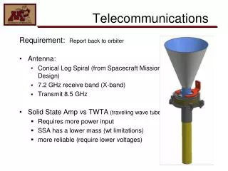
Typical Antenna Patterns • Slot G< 10 dBi • Dipole G<10 dBi • Horn G=10-20 dBi
Parabolic Reflector Antenna parallel beams focal point • D – diameter • - wavelength z - efficiency
Lobes • Backlobes • Sidelobes
Modulation • Definition • Altering a signal to make it convey information (either analog or digital) • AM (Amplitude Modulation) • Changes amplitude (frequency constant) • FM (Frequency Modulation) • Changes frequency (amplitude constant) Frequency modulation
Modulation (cont’d) • Changing the phase of the signal • For digital data, these methods are also called • ASK – amplitude shift keying • FSK – frequency shift keying • PSK – phase shift keying
Link Budget • Allocation of various losses and gains in the communication link between Earth and the spacecraft • Similar to signal-to-noise ratio, but Eb/No pertains to digital data
Link Requirements • For data • (Eb/No)estimated – (Eb/No)required 3 dB • For commands • (Eb/No)estimated – (Eb/No)required 20 dB • This difference is known as the link margin
P – transmitter power Ll – line loss (between transmitter and antenna) Gt – transmitter antenna gain Ls – space loss (inverse square in distance) k – Boltzmann’s constant La – transmission path loss (atmosphere and rain absorption) Gr – receive antenna gain Ts – system noise temperature R – data rate Li – implementation loss (-2 dB) Terms
More Details • Calculate Link Margin = (Eb/No)est – (Eb/No)req Fig. 13-9, SMAD Acceptable BER
Example • If acceptable BER (bit error rate) is one bit error in every 100,000 bits, then BER=10-5 • Using BPSK modulation with Reed/Solomon coding, this requires an Eb/No=2.5dB • If BPSK is used without coding, Eb/No=9.5dB • Increase transmitter power by 7 dB • Multiplicative factor of 100.7=5 • Increasing the transmitter and receiver antenna gains by 7dB (combined) • Antennas then more sensitive to pointing errors
C&DH Prop. tank A/D Converter Microprocessor sensor Data Rates • For each sensor, data rate • Sample size is determined based upon required level of accuracy • Example – temperature sensor needed to monitor propellant tank temperature in range -10C to +80C • Amplitude range=80C-(-10C)= 90C
80C -10C Data Rates (cont’d) • Sensor generates voltage proportional to temperature • A/D converter generates a digitized representation of this temperature – an n-bit word • Number of quantized levels that are represented = 2n • Quantization step here= Quantized steps
Data Rates (cont’d) • Example continued So, if n=8, then quantized step = 0.35oC and Eq = 0.175oC Typically, one needs to find the required value of n. Using same example, if required Eq 0.05oC, then quantized step = 0.1oC and
Sample Rate • Determined based upon estimated rate of change of quantity being measured • Examples • Thermal sensors typically sample at low rates (once per minute) • Attitude sensors sample at high rates, especially during attitude maneuvers (1-5 samples/sec)
Sampling Oscillatory Phenomena • Must sample at 2.2 times the highest frequency present • Human voice has frequency range of ~3.5 KHz • Sample at 7.7 KHz (7,000 samples/second) • Commercial audio (telephony) requires ~8 bits/sample • Data rate = 7,700 samples/sec x 8 bits/sample ~62,000 bits/sec (bps)
Data Compression • Compression/encoding allow lower data rates • Make use of repeated patterns in the data and/or transmit only parts of data that changes since previous sample • Voice data can be reduced to ~9.6 Kbps • Compressed video (videophone) ~28 Kbps • Full video with color 256 Mbps (~40 Mbps with coding)
Sensor A Microcomputer Microcomputer Microcomputer Modulator Transmitter Sensor B Main Computer Sensor C Telemetry • Packet telemetry format • Each sensor forms packet of data • When packet complete, microcomputer interrupts main computer • Main computer formats main block • Main block transmitted • Advantages • Flexible data rates for sensors • Disadvantages • Spacecraft processing more complex • Ground station equipment more complex
Error Detection and Correction • Once our telemetry data is set to transmit, we must concern ourselves with possible induced errors in the transmission • With digital data, there are several ways to check for errors • Parity check (with retransmission) • Error correction (without retransmission) Ref: Spacecraft Attitude Determination and Control, J.R. Wertz (ed), Reidel Publishing Co., 1978
Parity Check • Simplest method of detection • Example: • M = [1,1,0,0] = original message • Add another parity bit to M • M now becomes [1,1,0,0,p] • Even parity scheme: • m1+ m2 + m3+ m4 + p = even number p=0 • Odd parity scheme: • m1+ m2 + m3+ m4 + p = odd number p=1 • Receiving equipment then checks each message vector
Parity Check • Suppose receiving equipment receives: • M = [1,1,0,0,1] • If both transmitter and receiver are employing even parity scheme, then an error has occurred • m1+ m2 + m3+ m4 + p = 3; not an even number • Receiver requests retransmission • What if two bits are flipped? • Parity scheme fails (much lower probability of two bit flips than one bit flip)
Error Correction without Retransmission • Example self-correcting developed by Hamming • Extra set of bits equal in number to the original message bits added to message vector • Before: M = [a,b,c,d] • After: M = [p1,p2,p3,a,p4,b,c,d]
Hamming (cont’d) • Multiply MT by the Hamming matrix, to get S=HMT (syndrome vector)
Hamming (cont’d) • Need to determine the values of p1,p2,p3, and p4 • Set these such that S = [0,0,0,0]T (mod 2) (Any even number = 0 mod 2) • Arrangement of parity bits in M so that only one new parity bit is involved in each successive calculation of p1,p2,p3,p4
Hamming Example • Intended message vector: Mo=[0,0,1,1,1,1,0,0] • Received message vector: M1=[0,0,1,1,1,0,0,0] • Correction scheme • If s4= 0, then a, b, c, and d are correct • If s4= 1, then error occurred in message bit s1s2s3 (101)2=5
Hamming Example (cont’d) • M= [b0 b1,b2 b3,b4 b5,b6 ,b7] • M1=[0, 0, 1, 1, 1, 0, 0, 0 ] • Correct M1 is M1=[0, 0, 1, 1, 1, 1, 0, 0 ] • So the original message data is [1 1 0 0] [a b c d] Error
Probability of Errors – Simple Parity • If probability of error in 1 bit is 1%, probability of at least one error in a 4-bit message is 4% • Adding one parity bit increases error rate to 5% • Can detect, but not correct this error • Need to retransmit 5% of the data • Probability of 0.25% that error occurs in 2 or more of the original 4 bits
Probability of Errors – Hamming Code • Using the 8-bit Hamming code will increase probability of error to 8% • One bit error can be corrected • Errors in 2 bits of M will occur in 0.64% of messages received • Two bit errors cannot be corrected • Hamming will detect two errors, so retransmission can be requested • Undetected errors in 3 or more bits will occur in ~0.051% of the messages received.