Download
1 / 27
740 likes | 1.03k Views
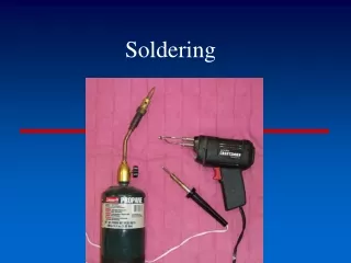
Soldering Technique. Introduction. Soldering is the process of joining two metals together to form an electrically and mechanically secure bond using heat and a third metal alloy known as solder. Poor soldered joints will fail, causing partial or complete failure of the circuit.

E N D
Introduction • Soldering is the process of joining two metals together to form an electrically and mechanically secure bond using heat and a third metal alloy known as solder. • Poor soldered joints will fail, causing partial or complete failure of the circuit. • NOTE: If part of a circuit fails, it could permanently damage a board, depending on the circuit design.
Soldering Equipments • The solder you will be using is a metal alloy of 60% tin 40% lead with a low melting point & a rosin core (acts like flux to help remove oxidation). • This is eutectic solder –goes directly from solid to liquid state when melted (no plastic phase). • Solder properties A) Melting point B) Mechanical resistance to fractures C) Cost • Solder poses a health hazard • Do not hold solder with your teeth • Do not lick, bite or place hands in mouth • Do not hold solder for excessive periods of time • Avoid breathing fumes… guaranteed it‟s not nicotine!
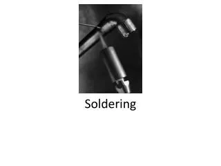
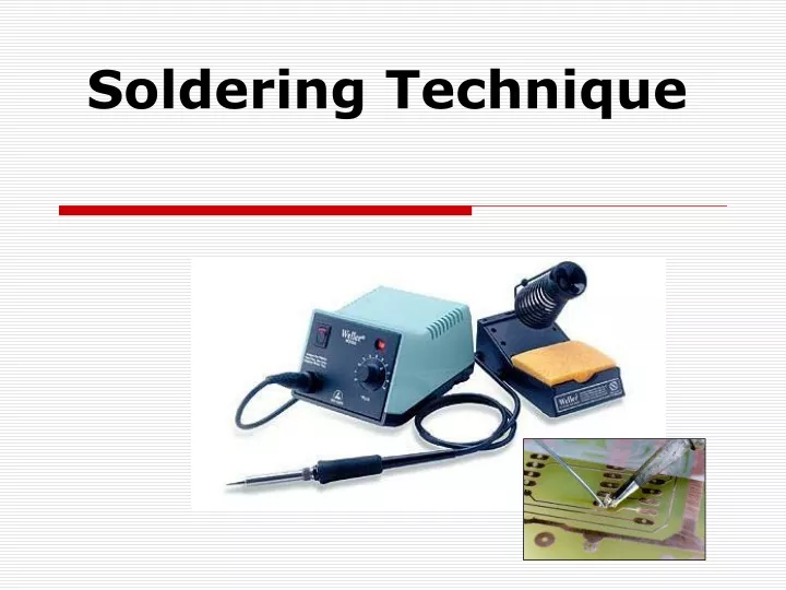
Soldering Equipments • Temperature-controlled iron. A soldering iron with electronic temperature control • Non-temperature-controlled iron. A low wattage (10 W to 25 W) pencil-type(not gun-type) • Sponge. A sponge is required for keeping tips clean for best heat transfer. • Tips. Currently, most tips sold for electronics work are iron-clad copper and have long life spans. • Solder sucker. Is a device which sucks the molten lead.
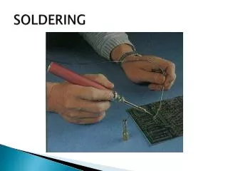
BASIC HAND SOLDERING TIPS • appropriate size and width is determined by the size of the connection to be made • ideally 2/3 to equal the diameter of the pad • tips should be correctly 'tinned’ at all times, by adding a small amount of solder to the hot tip
Soldering a Component Use a lead bending jig, if available, to form the component leads to the correct spacing If a bending jig is not on hand, grasp the leads, not the body, of the component with needle-nosed pliers and bend gently.
Soldering a Component Insert the component’s leads through the holes in the circuit board. The body should lie flat against the board without having to force it down. Turn the board over and gently bend the component leads outward to hold the component in place
ADD YOUR COMPONENT (example shown is a resistor)by pushing the wires through the holes you have drilled in your PCB.
ADD YOUR COMPONENT (example shown is a resistor)by pushing the wires through the holes you have drilled in your PCB. Bend over all of the wires you’re not going to solder now.
CLEAN THE POINT OF THE IRON - take away any dirt on a damp (not soaking wet) sponge when the iron is heated up. This will help your solder to flow properly.
”TIN” THE IRON. This just means you should melt a tiny bit of solder onto the point. Try to avoid breathing in the fumes - they can be harmful.
Soldering Iron
Move soldering iron until tip is touching wire & solder pad
Move solder to touch edge of tip. Solder lead
Hold until solder melts on tip by wire Solder lesd
Move solder in to form a small pocket Solder
Move soldering iron tip up. This will drag solder up with it. Solder
GOOD AND BAD ATTEMPTS GOOD:The join is complete and will hold in place. BAD:Not enough solder applied. No join.
GOOD AND BAD ATTEMPTS BAD:Copper track not heated long enough. No join. BAD:Copper track burned so no current can pass through. No join.
Soldering Inspection • What to look for: • Bond should be a cone and shiny. • Profile of bond should be concave, not convex. • Bond surrounds part completely…. not 99%. • Bond does not cover other connections. • How to fix problems: • Apply heat again, not as long as before, with clean iron. • Add a small amount of solder… very small. • If too much solder is applied, use a copper wick or solder sucker to remove the solder. Note: Solder sucker removes most of the solder. You will have to re-solder after this process. This may produce excessive heat on your part… possibly damaging it.
Good bonds • Here is a picture of a good bond. Note the concave cone, and the shiny metal. The second picture is a cross section of the wire soldered through a via (hole) in a PCB. Good soldering
Soldering Inspection • This is an example of not enough solder. • Note other bonds are shiny and surround the entire part. Bad soldering
Cold Joint • Can occur when not enough heat is applied
Parts Flush Mounted? • Your parts must be flush mounted on the board to avoid broken bonds. The picture on the right shows two bonds that are mechanically broken. Let the PCB take the stress, not your bonds.