Download
1 / 15
160 likes | 321 Views
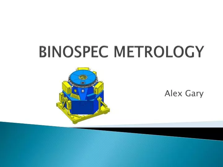
BINOSPEC METROLOGY. Alex Gary. Binospec. Astronomical spectrograph for the MMT Observatory on Mount Hopkins in Arizona 2007- project design completed by Harvard University Used extensively by the University of Arizona and other institutions . Binospec.

E N D
BINOSPEC METROLOGY Alex Gary
Binospec • Astronomical spectrograph for the MMT Observatory on Mount Hopkins in Arizona • 2007- project design completed by Harvard University • Used extensively by the University of Arizona and other institutions
Binospec • Binospec is an imaging spectrograph with dual 8'x15' fields of view • dual slitmasks which can hold up to 150 slitlets for multiobject spectroscopy. • Superior sky subtraction with these slitlets will allow Binospec to reach 3-4 magnitudes deeper than Hectospec • Binospecuses the fiber spectroscopy configuration of the corrector, which has built-in atmospheric dispersion compensation.
Calibration Screen • In order to allow the design to work with so many slitlets a callibration screen was necessary in order to assure proper viewing. • This is the specific part of the assembly that I was involved in.
The Metrology Stage • As the project came to fruition a precise method of measuring and checking key points and joints in the connecting structures was essential • Between manufacturing and assembly, metrology is required to troubleshoot any problems that may come up during assembly before assembly begins • As parts come in for assembly they were measured and compared to nominal coordinates to determine any problems or complications
Metrology Technique • The Metrology process involved a FARO Arm and CAM 2 Measure 10 Software. • The entire process of metrology involved a 3-Stage Process. • The Three Stages to the Metrology involved Set Up, Measurement, and Analysis.
Set Up • Set up involves both physical and virtual set up. • The piece to be measured had to strategically mounted to get all of the required measurements • A solid works model was uploaded to the CAM 2 Software and the desired planes and circles had to be selected before measurement could begin
Set Up (Physical and Virtual) • FARO Arm • Solid Works Model (Before Set Up) • Model in CAM 2 Software (Post Set Up)
Measurement • After Set Up is complete measurements can be taken with the FARO Arm. It is a rather simple process but involves attention to detail and care to make sure no simple mistakes are made.
Analysis • Analysis involves comparing the actual and nominal measurements, determining sources of error in either manufacturing or the measurement stage, and deciding on actions to be take on any error found. • Actions taken during the analysis stage can range from returning to the measurement stage, making slight modifications ourselves, or returning the entire part to the manufacturer.
Analysis Sample • CAM 2 Software allows does some of the analysis on its own. This is a sample of the analysis for the handling cart interface. • This crucial part had to be precisely manufactured so every plane and circle was analyzed with scrutiny (and passed)
Overall Summer Metrology Results • After a week and a half of Metrology we found no crucial problem so we began assembly. The entire frame assembly was simple with only one minor modification needed. • Beyond this the internal structure of the Calibrator Screen and Derotator Assembly had to be completed. • Recently other metrology and engineering decisions had to be made to make assembly run smoother