Download
1 / 11
110 likes | 120 Views
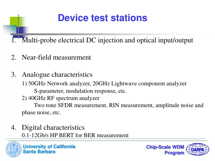
Device test stations. Multi-probe electrical DC injection and optical input/output Near-field measurement Analogue characteristics 1) 50GHz Network analyzer, 20GHz Lightwave component analyzer S-parameter, modulation response, etc. 2) 40GHz RF spectrum analyzer

E N D
Device test stations • Multi-probe electrical DC injection and optical input/output • Near-field measurement • Analogue characteristics • 1) 50GHz Network analyzer, 20GHz Lightwave component analyzer • S-parameter, modulation response, etc. • 2) 40GHz RF spectrum analyzer • Two tone SFDR measurement, RIN measurement, amplitude noise and phase noise, etc. • 4. Digital characteristics • 0.1-12Gb/s HP BERT for BER measurement
Multi-probe DC electrical injection and optical input/output Programmable multi-channel current driver Device mount with TE-cooler High-precision stages Probe holder Control injection current, input optical power and wavelength from tunable laser, capture output signal from optical power meter with GPIB by computer using Labview Lensed-fibers Multi-probe platform
Near-field measurement Long focus-distance lens Microscope CCD camera Near-field image recorded by computer High-precision 3-D stages Device mount Lensed-fiber
LD Controller TEC Controller A Two-tone SFDR Measurement for EAM RF pre-amplifier Lensed fiber TW-EAM RF Spectrum Analyzer Polarizer PD Pico-Ampere meter Bias-Tee DC power Supply Attenuator Combiner f1=10GHz Isolator 1 Isolator 2 f2=10GHz-100MHz
SFDR Measurement results for EAM 15mW optical input f1=9.9GHz f2=10GHz DC Bias=0.8V SFDR=121dB/Hz^4/5 TM TE f2 RF output (dBm) 2f2-f1 121 dB Noise floor 165dBm@1Hz RF input (dBm)
Modulation response measurement for DBR laser Lightwave component Analyzer DC bias Lensed- fiber DBR laser Bias-T Measurement setup 3-dB modulation bandwidth is about 20GHz.
RIN measurement for DBR laser Measurement setup Current and Temperature controller DC Bias Photocurrent Pico-Am-meter Photodetector Optical Power meter DC-block RF spectrum analyzer RF amplifier
10GHz RF Photocurrent RF Amp. DC Bias Bias-T DC Pico-Am-meter Fiber Coupler Tunable laser DBR-LD 10% RF amplifier DC-block RF spectrum analyzer Amplitude Noise measurement for 10Gb/s Gain-switched DBR-LD Pulses • Intensity noise with a peak at 5.2GHz • (the relaxation oscillation frequency) at 67.8mA. • RIN is -139dB/Hz at 5.2GHz. • Broadband RMS amplitude noise • is 0.005 and 0.01 over 24MHz-9GHz • at injection current 67.8mA and 53.4mA, respectively. • RMS SSB amplitude noise is 0.006 • over 40kHz-10MHz at injection current 67.8mA .
Phase Noise and Timing Jitter measurement setup 10GHz RF generator 10GHz+1.5MHz RF generator Phase Shifter (90o) Residual timing jitter measurement LO RF Amp. Low-frequency pre- amplifier Double Balanced mixer LPF Bias-T IF Low-frequency RF spectrum analyzer DC Fiber Coupler RF DBR-LD Tunable laser 10% Absolute timing jitter measurement DC-block RF amplifier RF spectrum analyzer Photodetector
Measurement Results for 10Gb/s Gain-switched DBR-LD Pulses Absolute RMS timing jitter is less then 1-ps over 40kHz-15MHz
BER Test Programmable controlled injection current SGDBR laser cw Wavelength converter cw E/O modulator EDFA OBPF Pre-amplifier RZ Transmitter OBPF Pattern generator Receiver data 01101111 BERT Clock