Download
1 / 20
200 likes | 340 Views
Customized Cyclic Test Device ME 462. Sponsor: Carrier Corporation Advisor: Dr. H. El-Mounayri May 3, 2007 Design Team: Mike Abel Braden Duffin Simon Marin Joe McGuire. Presentation Outline. Background Requirements Development Final Design Evaluation

E N D
Customized Cyclic Test DeviceME 462 Sponsor: Carrier Corporation Advisor: Dr. H. El-Mounayri May 3, 2007 Design Team: Mike Abel Braden Duffin Simon Marin Joe McGuire
Presentation Outline • Background • Requirements • Development • Final Design • Evaluation • Recommendations • Questions
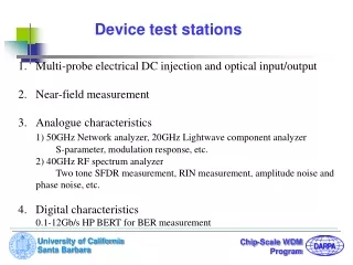
Design Objective • Design a custom cyclic corrosion device for testing material samples. • The device must replicate conditions encountered in actual furnace applications. • Environmental conditions include hot air, chemical exposure, and humidity.
Performance Requirements • Controlled temperature range of 70-400° Fahrenheit • Humidity: 85% • Corrosive Chemical Exposure • Controllable and variable cycle transitions (30-60 sec. transitions) • Other (weight, cost, size, power, safety)
Development • Concepts generation included QFD, functional flow analysis, function-concept mapping, decision matrix, etc… • Designed housing concept using ProEngineer • Researched commercially available components (heat element, fan, valves, chemical pump, etc…) • Performed analyses to determine necessary component performance • Redesigned housing to fit suitable components
Final Design (Front View) Valves Fume hood Representation Heat Chamber Cooling Fan Heating fan
Final Design (Rear View) Chemical / Water spray inlets External Cover Chamber Vent Drain Pan
Final Design (Internal View) Chemical Nozzle Water Nozzle Test Samples
Design Evaluation • Verification of the requirements was obtained from: • Procured component specifications • ProEngineer model geometry • Part weights and dimensions • Computational Fluid Dynamics (CFD) simulations
CFD Model and Boundaries Vent Heating Element Cool side valve Cooling Fan Heat side valve Heating Fan
Requirements Verification • CFD Analysis • Temperature range requirement: 70-400ºF • Temperature range achieved: 70-500ºF • Temperature transition time requirement: < 60 seconds • Actual time to heat chamber: > 200 seconds • Actual time to cool chamber: 25 seconds
Steady-state heating simulation • Demonstrates capability to exceed temperature requirement • Internal temperature is 475-500 ºF Flow streamlines colored by temperature
Cooling time simulation • Demonstrates cooling time capability • Simulation time is 25 seconds • Internal temperature drops from 500 to 80ºF
Heating time simulation • Demonstrates heating time capability • Simulation time is 200 seconds • Final Internal temperature is 340ºF • Needs optimization
Requirements Verification • Humidity: 85% (predicted, not verified) • Uniform Chemical Vapor Spray (based on procured nozzle and pump specs.)
Requirements Verification • Safe to be handled (warning: some heated surfaces and ventilation) • System maintenance and cleaning: All parts exposed to chemicals are stainless steel. All individual part weights are below 60 lbs. • Fits in hood dimensions (verified by ProE model) • Holds 6 coupons (Target: 2)
Requirements Verification • Powered by 110 V (based on procured components specs.) • System can be automated (All parts can be electrically controlled) • System Cost $2799 - $8389 depending on valve choice (Target: $3000)
Heat Cycle Recommendation • Objective: decrease time to heat chamber • Currently using preheated air to facilitate heating • Increase amount of preheated air: • Increase volume of heat chamber • Increase surface area of heat strip • Add heat strip • Add second heat chamber • Optimize air flow • Entry vents • Exit vent
Valve Recommendation • Objective: Meet initial budget requirements, minimize long term costs • Xomox butterfly valve: $3345 each • Highest quality heat and corrosion resistance • 2” long • McMaster swing check valve: $550 each • Lower quality heat and corrosion resistance • 6” long • Likely requires regular replacement • Design custom valve in house?