Download
1 / 25
250 likes | 501 Views
Fast Optical Scanning for Confocal Raman Tweezing Spectroscopy. Emanuela Ene. Abstract.

E N D
Fast Optical Scanning forConfocal Raman Tweezing Spectroscopy Emanuela Ene PHYS 5123 Optical Design Project
Abstract The Confocal Raman Tweezing Spectroscopy (CRTS) has the ability to provide precise characterization of a living cell without physical or chemical contact. In our nanotoxicity study, CRTS will be employed for monitoring in real time the chemical and functional changes in nanoparticle-embedded cells. PHYS 5123 Optical Design Project
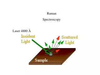
For a CRTS study a very stable optical trap is essential, so that extra cell instability is not induced. • Repeatability and stability of the collected Raman spectra during optical trapping may be achieved with automatic laser beam steering. • A two-axis acousto-optic deflector (AOD) and a piezo positioner are designed to be included in our existing Confocal Raman Tweezing Spectrometer (CRTS) in order to achieve fast and precise laser trap displacements. PHYS 5123 Optical Design Project
A perfect lens OSLO simulation is run for our Gaussian beam based CRTS. • Beam steering OSLO computations, in both transversal and axial directions, demonstrate the range for scan angles and for linear translation. • For a truncated Gaussian beam, employed in optical tweezing, we expect optical aberrations even for a perfect lens-like focusing objective. PHYS 5123 Optical Design Project
a) A single beam traps that part of a living cell with the highest refractive index. The trapped cell can have different orientations inside the trap. http ://www.uni - Mainz.de/FB/Medizin/Anatomie/Leube/images/ogolivingcell/jpg Images of a trapped budding yeast cell immediately after the trapping event (b), after 2 s (c) and 5 s (d). PHYS 5123 Optical Design Project
Outline The Confocal Raman Tweezing Spectroscopy has the ability to provide precise characterization of a living cell without physical or chemical contact. The CRTS allows the analysis of single cells in wet samples, in contrast with the classical micro Raman spectroscopy which utilizes dried samples. In a confocal setting, the collected signal comes just from a minimum volume around the trapped-excited object. In our nanotoxicity study, CRTS is used to monitor the chemical and functional changes in nanoparticles-embedded cells in real time. • Background – Our CRTS application • Experimental setup • Axial resolution • Confocal microRaman spectra PHYS 5123 Optical Design Project
halogen lamp PMT objective& sample DM3000 system L focus L collect P4 Monochromator L curvature Video camera BS Raman Imaging system BS imaging beam expander LLF P3 Experimental setup subt. filters HeNe Laser M2, M3 BPR P1 LLF Ar+ Laser M1 P2 Our Confocal Raman-tweezing system M – Silver mirror P – Pinhole LLF - laser line filter BS – beam-splitter BP - broad-band polarization rotator PHYS 5123 Optical Design Project
Proposed solution The problem addressed is monitoring living cells, via the CRTS technique for nanotoxicity studies. Both stability of the trap, for around eight hours of successive spectra collection, and repeatability are required. Optical trapping and manipulation can be realized using mechanical microstages or electric nanopositioning. The latter method is not only far more precise, but also assures stability and repeatability. Nanopositioning systems currently used for CRTS are: galvanic mirrors, piezo-controllers, and AODs. The automatic fast laser beam steering will allow moving the beam focus in 3D to “chase” the cell that will be trapped and analyzed. Thus we will eliminate any mechanical displacement, proven to be a source of misalignments, instabilities, and irreversible changes. A two-axis acousto-optic deflector (AOD) and a piezo-positioner are designed to be included in our existing Confocal Raman Tweezing Spectrometer (CRTS) in order to achieve fast and precise laser trap displacements. PHYS 5123 Optical Design Project
The advantage of choosing to fast steering the trap only in the x-y plan simplifies the confocal pinhole alignment. The pinhole will be initially aligned in the conjugate plane of the objective focal plane. This alignment will be stable while scanning the x-y plane in the range of 0-100μm (or 0-50mrad) for a pinhole size in the range 200-400μm. The alignment will be also stable when moving the infinity corrected objective on the z-optical axis of the setting in the range of 0-400 μm. If the position of the trap on the z-axis would be changed by controlling the laser beam divergence, as done in classical tweezing setups, the conjugate plane of the pinhole can not be kept fixed. PHYS 5123 Optical Design Project
Technical description The improved CRTS setup is shown in Fig. 1. Three alternatives for new parts that should be included are listed in Table 1. The effects of beam steering with the AODs and of displacing the objective with the piezo controller are shown in OSLO simulations. Potential problems which we may encounter are due to the thermal sensitivity and to the electric noise of the driving voltage for the AODs. We address these two weaknesses by designing a heat sink for the AODs and by including the highest precision voltage controllers on the market. PHYS 5123 Optical Design Project
Raman system Entrance slit Confocal pinhole Dual axis AOD 4X beam expander Laser Microscope objective piezo controlled Imaging system Fig.1 – the improved CRTS system PHYS 5123 Optical Design Project
Table 1 Specifications & Prices to electronically control the tweezing position . PHYS 5123 Optical Design Project
Preliminary results • Microscope objectives are complex systems of lenses, corrected for geometrical and chromatic aberrations; such an almost perfect system has more surfaces than we may handle in EDU version of OSLO; in the simulations we enter a PERFECT LENS with F=2mm and magnification 100X for our PLAN APOCHROMAT infinity corrected oil immersion objective • the object to be “imaged” is the incident laser beam • the laser beam is Gaussian, 632.8nm, is collimated, and has an expanded 6.0mm waist size • the expanded beam “fills” the 6.0mm-radius of the microscope aperture; the beam is truncated by this aperture to its 1/e2 diameter PHYS 5123 Optical Design Project
An 100X magnification immersion objective, under US Patent 5,978,147, comprises three groups of lenses and a total of 22 surfaces Microscope objectives are complex systems of lenses, corrected for geometrical and chromatic aberrations; such almost perfect systems have more surfaces than we may handle in EDU version of OSLO PHYS 5123 Optical Design Project
PERFECT LENS • “A perfect lens is that one that forms a sharp undistorted image of an extended object on a plane surface” (from the OSLO Reference manual). • OSLO uses perfect lenses obeying the exact laws of optics. The results when using these perfect lenses are different from modeling with paraxial lenses. • If the lens is to obey Abbe’s sine law, rays must emerge from the surface at a different height than they enter. A real perfect lens cannot be infinitely thin. • Abbe’s sine law, valid for aplanatic (coma free) lenses: • with • U, U’ the angles which the corresponding rays in the object and image spaces make with the axis of the system • u, u’ the slopes of the corresponding rays in the object and image spaces PHYS 5123 Optical Design Project
PERFECT 100X , F=2mm, focusing LENS DATA *LENS DATA perfect 100x f=2 focusing lens SRF RADIUS THICKNESS APERTURE RADIUS GLASS OBJ -- 202.000000 6.000000 AIR AST ELEMENT GRP -- 1.732985 AS AIR * 2 PERFECT 2.020000 S 1.732985 S OIL M * PERFECT IMS -- -- 0.060000 S PHYS 5123 Optical Design Project
PERFECT 100X, F=2mm, focusing LENS No aberrations PHYS 5123 Optical Design Project
oil layer: noil=1.51536@632.8nm t=(0.1- 0.6)mm cover glass: ncover= 1.52216@632.8nm t=0.17mm sample: n=1.33 t=1.75mm The 100X on the short conjugate side PERFECT LENS with F=2mm gives for a 632.8nm Gaussian beam a 2μm minimum waist *LENS DATA tweezing INITIAL SRF RADIUS THICKNESS APERTURE RADIUS GLASS SPE NOTE OBJ -- 1.0000e+03 6.000000 AIR AST ELEMENT GRP -- 6.000000 AS AIR * 3 PERFECT 1.400000 6.000000 S OIL M * PERFECT 4 -- 0.170000 4.804800 S COVER M 5 -- 0.356946 4.299109 S SAMPLE M IMS -- -- 0.0019921 S PHYS 5123 Optical Design Project
The beam profile in the image plane for the OSLO model The cover glass and the solution with cells change the conditions for a perfect lens The tweezing spot profile for a Gaussian beam (T>2) Truncation factor: T=D_beam(1/e2) / D_apert PHYS 5123 Optical Design Project
The beam profile in the image plane, the OSLO model, for truncated Gaussian beams employed in optical tweezingCalculations based on a paraxial ray trace may be invalid for a truncated Gaussian beam OSLO computes the diffraction image of a point object (the Point Spread Function) from the information of the geometric wavefront. For a truncated Gaussian beam entering our tweezer the central normalized energy peak is 0.48. The orresponding trapping force, in the spring-like trap, is 70% of the full power force. T=1 Truncation factor: T=D_beam(1/e2) / D_apert Note: the PSF algorithm results depend on the number of points in the sampling grid PHYS 5123 Optical Design Project
Trap image (tweezing focus) in the X-Y plane for a Gaussian beam PHYS 5123 Optical Design Project
1 2 3 Steering the tweezing focus in the X-Y plane for a Gaussian beam AOD – objective distance: -202mm Both AOD’s are driven for equal scan angles on the X and Y directions PHYS 5123 Optical Design Project
Steering the tweezing focus on the Z-axis for a Gaussian beam t_oil=0.6mm 1 t_oil=0.5mm Trap position moves on the z-axis when the immersion oil layer is compressed by the piezo-controlled objective. The cover glass is 0.17mm thick for all three shown positions but the beam focusing and aperture change. The OSLO simulations show: 1) focus in the cover; 2) focus in the sample, 0.030mm from the cover; 3) focus in the sample, 0.381mm from the cover 2 t_oil=0.1mm 3 PHYS 5123 Optical Design Project
Summary • A perfect lens OSLO simulationhas shown how a perfect lens focuses a Gaussian beam • Beam steering OSLO computations, in both transversal and axial directions, have demonstrated the range for scan angles and linear translation • For a truncated Gaussian beam, employed in optical tweezing, we expect aberrations even when focusing with a perfect lens PHYS 5123 Optical Design Project
References • Carls, J.C. et al, Time- resolvedRaman spectroscopy from reacting optically levitated microdroplets, Appl. Optics, 29, 1990, pp. 2913-18 • Cao, Y.C. et al, Raman Dye-Labeled Nanoparticle Probes for Proteins , J.Am. Chem. Soc., 125 (48), 14676 -14677, 2003 • C. Xie, Y-qing Li, Confocal micro-Raman spectroscopy of single biological cells using optical trapping and shifted excitation techniques, J.Appl.Phys., 2003, 93(5), 2982-2986 • Owen, C.A. et al ,In vitro toxicology evaluation of pharmaceuticals using Raman micro-spectroscopy, J. Cell. Biochem., 2006, 99, 178-186 • Volpe, G. et al, Dynamics of a growing cell in an optical trap, Appl. Phys. Lett., 2006, 88, 231106-231108 • Creely, S.M. et al, Raman imaging of neoplastic cells in suspension, Proc. SPIE, 2006, 6326: 63260U • Shaevitz, J.W. , A practical Guide to Optical Trapping, web resource at www.princeton.edu/~shaevitz/links.html PHYS 5123 Optical Design Project