Download
1 / 34
340 likes | 348 Views
Learn about the concepts of current, resistance, voltage, and power in electric circuits, and how they are related to each other. Explore series, parallel, and combination circuits using Ohm's Law.

E N D
Current, Resistance, VoltageElectric Power & EnergySeries, Parallel & Combo Circuits with Ohm’s Law
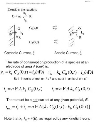
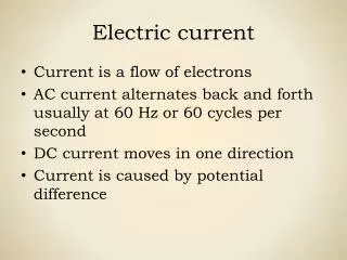
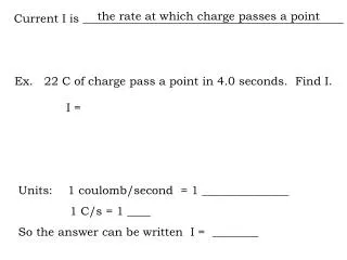
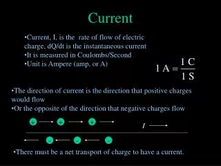
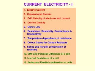
Current (I) • The rate of flow of charges through a conductor • Needs a complete closed conducting path to flow • Measured with an “ammeter” in amps (A) named for Ampere – French scientist
Voltage (V) • Electric potential difference between 2 points on a conductor • Sometimes described as “electric pressure” that makes current flow • Supplies the energy of the circuit • Measured in Volts (V) using a voltmeter
Resistance (R) • The “electrical friction” encountered by the charges moving through a material. • Depends on • Material • Length • Temperature • Cross-sectional area of conductor • Measured in Ohms (Ω)
Ohm’s Law • A relationship between voltage, current, and resistance in an electric circuit • used to make calculations in all circuit problems • V = potential difference (voltage) in volts • I = electric current in amperes (amps , A) • R = resistance in ohms ( )
R1 R2 R3 Series Circuits • Current can only travel through one path • Current is the same through all parts of the circuit. • The sum of the voltages of each component of the circuit must equal the battery. • The equivalent resistance of a series circuit is the sum of the individual resistances. V I
R1=1 Ω IT 6V R2=2 Ω Solving a Series Circuit Step 1: Find the equivalent (total) resistance of the circuit Step 2: Find the total current supplied by the battery Step 3: Find Voltage Drop across each resistor. Note: Voltage adds in series and voltage drops should add to the battery voltage, 3V+3V=6V
Electric Power (Watts) units using
Electric Energy • Electric energy can be measured in Joules (J) or Kilowatt hours ( kWh ) • for Joules use Power in watts and time in seconds • for kWh use Power in kilowatts and time in hours
Example Problem #1 An electric furnace is connected across a 117 V circuit. The furnace dissipates 3.5 kW of power in the form of heat. a) What is the resistance of the furnace? b) How much heat does the furnace produce in 5 min?
Example Problem #2 Your bedroom lights are four 60 W bulbs. a) If they are each hooked up to 120V, how much current do they each draw? b) What is the resistance of each bulb? c) If the lights are on for 3 hours a day, how much energy (in kWh) do they consume in 30 days? d) If electricity costs $0.12 per kWh, how much does it cost to operate the lights for a month?
R1 R2 V R3 Parallel Circuits • Current splits into “branches” so there is more than one path that current can take • Voltage is the same across each branch • Currents in each branch add to equal the total current through the battery
R2=6Ω 12V R3=4Ω R1=12Ω Solving a Parallel Circuit Step 1: Find the total resistance of the circuit. Step 3: Find the current through each resistor. Remember, voltage is the same on each branch. Step 2: Find the total current from the battery. Step 4: Check currents to see if the answers follow the pattern for current. The total of the branches should be equal to the sum of the individual branches.
Example problem A circuit has 3 resistors in parallel: 3W, 3W and 6W attached to a 10V battery. Draw the circuit, then find the voltage across and the current through each resistor.
Reading Resistors Color bands: digit, digit, mulitpler, tolerance
Review Worksheet Omit 1 and 3 on the front. Answers online Due Tues – Parallel WS, Review WS
Solving a Parallel Circuit R2=2Ω 12V R3=3Ω R1=1Ω Step 1: Find the total resistance of the circuit. Step 3: Find the current through each resistor. Remember, voltage is the same on each branch. Step 2: Find the total current from the battery. Step 4: Check currents to see if the answers follow the pattern for current. The total of the branches should be equal to the sum of the individual branches.
Combo Circuits with Ohm’s LawWhat’s in series and what is in parallel? A B It is often easier to answer this question if we redraw the circuit. Let’s label the junctions (where current splits or comes together) as reference points. 5Ω 1Ω 3Ω 6Ω 15V D C 4Ω 7Ω 2Ω 6Ω 4Ω C 2Ω B 1Ω D 7Ω A 3Ω 5Ω 15V
Combo Circuits with Ohm’s LawNow…again…what’s in series and what’s in parallel? 6Ω 4Ω 2Ω C B The 6Ω and the4Ω resistors are in series with each other, the branch they are on is parallel to the 1Ω resistor. The parallel branches between B & D are in series with the 2Ω resistor. The 5Ω resistor is on a branch that is parallel with the BC parallel group and its series 2Ω buddy. The total resistance between A & D is in series with the 3Ω and the 7Ω resistors. 1Ω D A 7Ω 3Ω 5Ω 15V
Combo Circuits with Ohm’s LawFinding total (equivalent) resistance 6Ω 4Ω 2Ω C B To find RT work from the inside out. Start with the 6+4 = 10Ω series branch. So, 10Ω is in parallel with 1Ω between B&C… Then, RBC + 2Ω=2.91Ω and this value is in parallel with the 5Ω branch, so… 1Ω D A 7Ω 3Ω 5Ω Finally RT = RAD +3 + 7 = 1.84 + 3 + 7 RT = 11.84Ω 15V
Combo Circuits with Ohm’s LawSolving for current and voltage drops in each resistor RT = 11.84Ω IT=1.27A IT=1.27A 6Ω 4Ω 2Ω C Then… B The total current IT goes through the 3Ω and the 7Ω and since those are in series, they must get their chunk of the 15V input before we can know how much is left for the parallel. So… 1Ω D A 7Ω 3Ω So… Since parallel branches have the same current, that means the voltage across the 5Ω resistor V5Ω=4.84V and the voltage across the parallel section between B&C plus the 2Ω is also 4.84V 5Ω 15V
Combo Circuits with Ohm’s LawSolving for current and voltage drops in each resistor (continued) I2Ω=0.81A I5Ω=0.46A IT=1.27A IT=1.27A Known values from previous slide. 6Ω 4Ω To calculate the top branch of the parallel circuit between points A & D we need to find the current and voltage for the series 2 Ω resistor. Since the current through the resistor plus the 0.92A for the bottom branch must equal 1.3A. 2Ω C To calculate the current through the 5Ω resistor… B 1Ω D A 7Ω 3Ω 5Ω 15V So…
Combo Circuits with Ohm’s LawSolving for current and voltage drops in each resistor (continued) I6Ω=I4Ω =0.068A Known values from previous slide. I1Ω=0.68A I2Ω=0.81A I5Ω=0.46A IT=1.27A IT=1.27A 2Ω Next we need to calculate quantities for the parallel bunch between points B&C. The voltage that is left to operate this parallel bunch is the voltage for the 5Ω minus what is used by the series 2Ω resistor. The 1Ω resistor gets all of this voltage. Finally we need to calculate the current through the 6Ω and 4Ω resistors and the voltage used by each. C B 6Ω 4Ω 1Ω D A 7Ω 3Ω All we need now is the voltage drop across the 6Ω and 4Ω resistors. So… 5Ω 15V THE END!
Kirchoff’s Laws Law of Loops ( or Voltages) treats complex circuits as if they were several series circuits stuck together. So…the rules of series circuit voltages allows us to write equations and solve the circuit. orΣVinput = ΣVdrops Law of Nodes (or Currents) The total of the currents that enter a junction (or node) must be equal to the total of the currents that come out of the junction (or node). orΣIin = ΣIout We use this law already in general when we add currents in the branches of a parallel circuit to get the total before it split into the branches.
Kirchoff’s Laws of Voltage writing the equations Draw current loops so that at least one loop passes through each resistor. Current loops must NOT have branches. Use ΣVinput = ΣVdropsfor each current loop to write these equations. Remember that current is a vector so if multiple currents pass through a resistor, the total is the vector sum of the currents assuming the current loop you are writing the equation for is positive. R1 R4 R2 V R5 IA IB IC R6 R3 R7 Loop A V= IA R1+(IA- IB) R2+IA R7 Loop B 0 = (IB- IA)R2+(IB- IC)R4+IB R3 Loop C 0 = (IC- IB)R4+ ICR5+IC R6
Kirchoff’s Law of Voltageputting numbers in the equations 1. Draw current loops so that at least one loop passes through each resistor. Current loops must NOT have branches. 2. Write an equation for each loop. 3. Solve the system of equations for all of the unknowns using a matrix (next slide) 3Ω 15V 5Ω 1Ω IA IB IC 6Ω Loop A 15V = IA (3Ω)+(IA- IB) (5Ω)+IA (7Ω) 15 = 3IA+5IA-5IB+7IA 15 = 15 IA - 5 IB + 0 IC Loop B 0 = (IB- IA)(5Ω)+(IB- IC)(1Ω)+IB (2Ω) 0 = 5IB – 5IA +1IB -1IC+2IB 0 = -5 IA + 9 IB - 1 IC Loop C 0 = (IC- IB)(1Ω) + IC (6Ω) +IC (4Ω) 0 = 1IC-1IB+6IC +4IC 0 = 0 IA -1 IB + 11 IC 4Ω Note: you must have coefficients for each unknown (even if it is zero) in every current loop equation. 7Ω 2Ω
Kirchoff’s Law of Voltage setting up and solving the matrix for IA, IB, and IC Beginning with the system of equations we wrote on the previous slide, we need to express these in matrix form to solve for the 3 unknowns 3Ω 15 = 15 IA - 5 IB + 0 IC 0 = -5 IA + 9 IB - 1 IC 0 = 0 IA -1 IB +11 IC 15V 5Ω 1Ω IA IB IC 6Ω IA IB IC 15 0 0 • -5 0 • -5 9 -1 • 0 -1 11 In a normal algebra equation Ax=B, the solution is x = B/A, however matrix operations do not allow for division so instead, after you create the matrices, you will use them in the following operation. x=A-1B. The answer will be in matrix form containing all of the unknowns in the order they were set up. 4Ω * = 7Ω 2Ω coefficients unkowns answers A * x = B Create matrix A and B in your calculator. (Matrx> >Edit, then choose A or B )
Kirchoff’s Laws of Voltage Interpreting the answers to the matrix problem 3Ω 15V 5Ω 1Ω IA IB IC 6Ω A * x = B After performing the operationx=A-1B, the calculator will give you a matrix answer (the number of decimal places will depend on the calculator settings) like below. IA IB IC 15 0 0 • -5 0 • -5 9 -1 • 0 -1 11 4Ω Using these current loop values we can now evaluate current, voltage, and power through any resistor in the circuit. * = 7Ω 2Ω So now we know that IA = 1.23A, IB=0.69A and IC = 0.063A Now what? 1.23 0.69 0.063 IA IB IC Example: for the 3Ω resistor, only IA passes through it so the I3Ω= 1.23 A, the voltage is V=IR=1.23A*3Ω=3.69V, and power, P=I2R= (1.23)2*3Ω = 4.54 W = coefficients unkowns answers
Kirchoff’s Laws of Voltage But what if the resistor you ask me about is shared by two current loops? Yikes! So now we know that IA = 1.23A, IB=0.69A and IC = 0.063A IA IB IC 1.23 0.69 0.063 3Ω = 15V 5Ω 1Ω IA IB IC 6Ω Let’s evaluate the 5Ω resistor: Since it is shared by current loops A and B, the current is the vector sum of the two. In this case IA & IB pass through the resistor in opposite directions so…I5Ω= IA-IB=1.23A-0.69A=0.54A . The voltage drop is calculated V5Ω=I5ΩR=0.54A*5Ω=2.7V. The power dissapatedis P=I5Ω2*R=(0.54A)2*5Ω=1.46 W. 4Ω 7Ω 2Ω
IT I2 I1 2 Ω 10V 1 Ω IT I2 1 Ω Node 3 Ω Kirchoff’s Law of Nodes 2 Ω IT=I1+I2 The current entering one node is equal to the sum of the currents coming out
Voltmeter and Ammeter • Ammeter • measures current in amps or mA • used in series • Voltmeter • measures voltage • used in parallel
Resistivity (ρ) • Property of material that resists the flow of charges (resistivity, ρ, in Ωm) • The inverse property of conductivity • Resistivity is temperature dependent…as temperature increases, then resistivity increases, and so resistance increases.