Download
1 / 22
270 likes | 776 Views
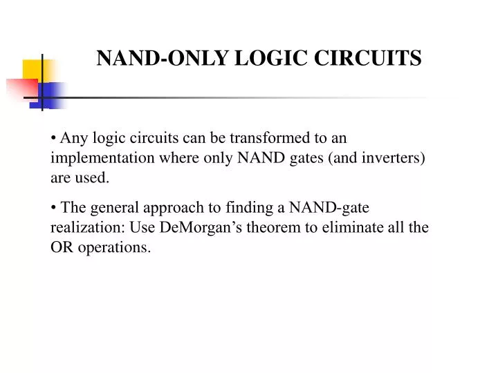
NAND-ONLY LOGIC CIRCUITS. • Any logic circuits can be transformed to an implementation where only NAND gates (and inverters) are used. • The general approach to finding a NAND-gate realization: Use DeMorgan’s theorem to eliminate all the OR operations. NAND-ONLY LOGIC CIRCUITS. (Example)

E N D
NAND-ONLY LOGIC CIRCUITS • Any logic circuits can be transformed to an implementation where only NAND gates (and inverters) are used. • The general approach to finding a NAND-gate realization: Use DeMorgan’s theorem to eliminate all the OR operations.
NAND-ONLY LOGIC CIRCUITS (Example) F = A + B • (C + D’) = A + B • (C’D)’ Note that (C’D)’ = C + D’ and (A’X’)’ = A + X F = (A’ • (B • (C’D)’)’)’ Now there is no OR operation in the Boolean expression. Note that A NAND B = (AB)’
F= (A’ • (B • (C’D)’)’)’ The logic circuit for this function is given by: We can also use the same procedure to do NOR only gates.
Ch2. Decoder Dr. Bernard Chen Ph.D. University of Central Arkansas Spring 2009
Integrated Circuits • An integrated circuit is a piece (also called a chip) of silicon on which multiple gates or transistors have been embedded • These silicon pieces are mounted on a plastic or ceramic package with pins along the edges that can be soldered onto circuit boards or inserted into appropriate sockets
Integrated Circuits • SSI, MSI, LSI: They perform small tasks such as addition of few bits. small memories, small processors • VLSI Tasks: - Large memory - Complex microprocessors, CPUs
Examples of Combinational Circuits • a) Decoders • b) Encoders • c) Multiplexers • d) Demultiplexers
Decoder • Accepts a value and decodes it • Output corresponds to value of n inputs • Consists of: • Inputs (n) • Outputs (2n , numbered from 0 2n - 1) • Selectors / Enable (active high or active low)
2-to-4 Decoder: NAND implementation Decoder is enabled when E=0 and an output is active if it is 0
Decoder Expansion • Decoder expansion • Combine two or more small decoders with enable inputs to form a larger decoder • 3-to-8-line decoder constructed from two 2-to-4-line decoders • The MSB is connected to the enable inputs • if A2=0, upper is enabled; if A2=1, lower is enabled.
Combining two 2-4 decoders to form one 3-8 decoder using enable switch The highest bit is used for the enables
Combinational Circuit Design with Decoders • Combinational circuit implementation with decoders • A decoder provide 2n minterms of n input variables • Since any Boolean function can be expressed as a sum of minterms, one can use a decoder and external OR gates to implement any combinational function.
Combinational Circuit Design with Decoders Example Realize F (X,Y,Z) = Σ (1, 4, 7) with a decoder: